background image

166

en | System menus and dialogs

Security Escort

2018.03 | SE3v1.0 | DOC

Technical Reference Manual

Robert Bosch (SEA) Pte Ltd

Test the new transmitter again. You should see a green light on a nearby SE receiver, and this
dialog should automatically disappear from the screen, confirming that the change was
successful.

10.2

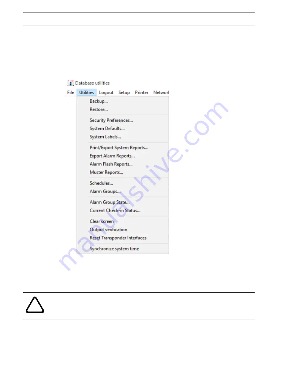
Utilities menu

From this menu, key operators can backup or restore the databases for the system, set the
options for the operation of the system, clear the map screen, and other features.

Figure


10.7: Utilities menu

10.2.1

Backup

This feature provides a convenient process for saving the information in the databases to
backup files.

!

Warning!

To prevent the accidental loss, the databases should be backed up at least once a week to
multiple backups. At least one of these backup copies should be kept in a different location
from the Central Console’s location.

Содержание SE3000 Series

Страница 1: ...Security Escort SE3000 Series en Technical Reference Manual ...

Страница 2: ......

Страница 3: ...or SE receivers 21 4 2 2 Number of outdoor SE receivers 22 4 2 3 Allowance for special coverage requirements 23 4 2 4 Number of SE coordinators and SE receivers 23 4 3 Pre installation coverage verification 23 4 3 1 Verify each potential SE receiver location 23 4 3 2 Indoor SE receiver installation Summary 25 4 3 3 Outdoor SE receiver installation Summary 25 4 4 Post installation after survey 26 4...

Страница 4: ...nt using Utility tool 82 8 1 Operations for the SE coordinator 82 8 1 1 Scanning SE coordinators 82 8 1 2 Modifying SE coordinator network settings 83 8 1 3 Uploading SE coordinator firmware 85 8 2 Operations for the SE receiver 87 8 2 1 Scanning SE receivers 87 8 2 2 Uploading SE receiver firmware 88 8 2 3 Adding available SE receiver to the SE coordinator 90 8 2 4 Removing connected SE receiver ...

Страница 5: ...base 153 9 10 1 Edit Operator s Database Record 154 9 10 2 Authority Level 156 9 11 Reports database 156 9 11 1 Statistics 157 9 11 2 Map 158 9 11 3 Edit Data 158 9 11 4 Delete 159 9 11 5 Locate Key 159 9 11 6 Key Select 160 9 11 7 Incomplete 161 9 12 System redundancy 161 10 System menus and dialogs 162 10 1 File menu 162 10 1 1 Locate transmitters 162 10 1 2 Maintenance alarm database 162 10 1 3...

Страница 6: ...99 10 4 9 Receiver test 202 10 4 10 Network status 203 10 4 11 System status 205 10 4 12 System preferences 207 10 4 13 Transponder comm port setup 207 10 4 14 Remote comm port setup 208 10 4 15 Remote setup 208 10 4 16 Remote connection 208 10 4 17 Pager setup 208 10 4 18 Send pager message 210 10 4 19 Utility tool 211 10 4 20 Email Setup 211 10 5 Printer menu 214 10 5 1 Select alarm printer 214 ...

Страница 7: ...on a live system without an authorized software key Copy the program into another computer only for backup purposes in support of your use of the program on one Security Escort system You may NOT Transfer this program or license to any other party without the express written approval of Bosch Security Systems 1 3 Limited warranty Bosch Security Systems warrants that the program will substantially ...

Страница 8: ...ter programs or data the cost of any substitute program claims by third parties or for other similar costs Bosch Security Systems does not represent that the licensed programs may not be compromised or circumvented In no case shall Bosch Security Systems liability exceed the amount of the license Some states do not allow the exclusion or limitation of implied warranties or limitation of liability ...

Страница 9: ...r tracking guard tour Post alarm tracking and alarm map recall System capabilities perfect for campus and community environments 2 2 Emphasis on reliability Supported by a multi million dollar company Extensive field testing under maximum abuse conditions from 20 F to 120 F Supervised system communication Low battery user and system operator notification Archived retrieval of system activity Paten...

Страница 10: ...ation and integration in any installation These features ensure system integrity and the comfort that when assistance is needed help is just a click away User Self Test Assures you that your transmitter is working Battery condition sent with every transmission Each test verifies system integrity Logs each test performed for easy access and reporting Can be performed indoors and outdoors Ensures us...

Страница 11: ...ions from SE transmitters SE coordinators are devices that control groups of SE receivers connected to them by wire Each SE coordinator relays alarm and test signals from its SE receivers to the Central Console In addition the SE coordinator tests for device and wiring faults and transmits problem conditions to the Central Console The Central Console consists of a computer plus an optional backup ...

Страница 12: ...r up to 5 000 users Contact Bosch Security Systems Customer Service or refer to website for the latest transmitter models The following table indicates the existing parts that are compatible with the new parts of the Security Escort system Part Name Description Enclosures and Housings AE3 Large enclosure 51 5 cm x 37 5 cm 20 25 in x 14 75 in AE1 Small enclosure 36 8 cm x 31 8 cm 14 5 in x 12 5 in ...

Страница 13: ...nosis of system problems usually with only one person being required The system software also continually monitors the status of each SE coordinator to ensure it is functioning correctly Versions There are several versions of the software available The number of users the system will support defines each version The following table lists the available models and number of supported users Model Use...

Страница 14: ...nclosures It is always mounted indoors The devices are connected to the SE coordinator by means of a multi drop RS 485 twisted pair wire Each bus is capable of supporting up to 15 SE receivers excluding the SE coordinator A Security Escort system supports up to 1024 SE coordinators Configuration Each SE receiver is identified to the SE coordinator by an address which is set during system installat...

Страница 15: ...nd determine the subscriber s location graphically Compatible Enclosures AE_100 indoor enclosure AE_101 outdoor enclosure Temperature Range 30 C to 65 C 22 F to 149 F Primary Power Source Power over Ethernet PoE Secondary Power Source 24 VDC in Input 2 analog inputs 4 state supervised monitoring Output 2 relay outputs relay dry contact 1A 30 VDC Antenna Type Internal Sensitivity Adjustments 100 dB...

Страница 16: ...ically mounted on the sides of buildings and on light posts Outdoor SE receivers do not have the visible red and green LEDs Outdoors the strobe lights connected to the SE receivers flash to acknowledge a successful test Function during an alarm In the event of an alarm the SE receivers detect an alarm signal from an SE transmitter and send this information to the SE coordinator The SE coordinator ...

Страница 17: ... supervision tracking alarm map recall and more Internal antenna User replaceable battery with four year life Belt clip attachment Optional silent manual alarm Low battery indication Optional holster for common security belt sizes Description The SE personnel transmitter contains a unique code which is associated with the user at the time the transmitter is assigned When the user generates an alar...

Страница 18: ...E receiver pressing the manual test button performs a test If the test is successful a small green light will flash on the indoor SE receiver or the strobe will flash briefly There will be no response at all if the test fails If the test fails the user should contact the Security Office as soon as possible When the SE transmitter is tested a special low battery message is included in the transmiss...

Страница 19: ...nsmitter s location During periods of inactivity the transmitter sends one status and location report to the Central Console every hour To reset the transmitter restore all device conditions such as tamper loop and magnet to normal Manual Duress Alarm During an alarm the transmitter automatically continues to transmit every 7 seconds providing the most current location information Low Battery Indi...

Страница 20: ...ts and specifications Security Escort 2018 03 SE3v1 0 DOC Technical Reference Manual Robert Bosch SEA Pte Ltd Notice The point tracking transmitter is only compatible with other equipment using the same radio frequency band ...

Страница 21: ...may be times when the computed location may appear to be on the other side of the wall The Security Escort system was designed to provide a computed alarm location typically within 7 5 m 25 ft of the actual location when indoors and a computed alarm location typically within 15 m 50 ft of the actual location outdoors Any deviation from the following installation guidelines will degrade the compute...

Страница 22: ...loor x number of floors 6 x 4 24 24 SE receivers for the building Figure 4 1 Determining the Number of Indoor SE receivers Required 1 SE receivers 6 units 4 25 m 80 ft 2 60 m 200 ft 5 25 m 80 ft 3 30 m 100 ft For the best location accuracy consistent SE receiver spacing is important Do not place SE receivers significantly closer in one section of a building than another section 4 2 2 Number of out...

Страница 23: ...as 4 2 4 Number of SE coordinators and SE receivers Assume that one SE coordinator will be installed per building for indoor installations If wiring can be run from other buildings or from outdoor SE receivers they may be connected to that SE coordinator All outside wiring must be under ground or in metal conduit Each SE coordinator can handle 15 SE receivers only However it is a good idea to leav...

Страница 24: ...ould not exceed 25 m 80 ft indoors and 90 m 300 ft outdoors Mount SE receiver 2 at this location or closer to SE receiver 1 Using an SE coordinator SE receivers and laptop computer to determine SE receiver location Notice System software and area map must be installed on laptop computer to use this method Before the SE receivers are mounted an SE coordinator with long RS 485 wires connected to the...

Страница 25: ...ng two protected buildings sharing a common wall with floor levels that do not match Ask the customer which building has areas of greater concern and favor the recommended mounting heights in that building The recommended 25 m 80 ft maximum indoor spacing grid should be maintained throughout both buildings as if the wall in question was not there Mounting heights only for those SE receivers at or ...

Страница 26: ...mal indoor and outdoor recommendations The building is near the boundary of the protected area with or without a fence at the boundary The SE receivers at the boundary of the protected area near the building should be spaced about the same as those in the building approximating the same grid as used in the building The building is adjacent to a large protected outdoor area that extends for more th...

Страница 27: ...d Using a standard subscriber SE transmitter 1 This method requires two people with radio contact between them One person operates the computer running the Security Escort software and the other takes the subscriber SE transmitter to the area to be tested 2 Press the alarm on the SE transmitter and remain at the spot where you transmitted 3 The computer operator acknowledges the alarm and accurate...

Страница 28: ...ould also generate alarms in areas adjacent to the area with the problem to see if they are also affected Using a maintenance SE transmitter with two people 1 The two people must have radio contact between them One person operates the computer running the Security Escort software and the other takes the maintenance SE transmitter to the area to be tested 2 At the computer select menu File Maintena...

Страница 29: ...building in one area move the closest SE receiver in the Transponder Database to that area a little further into the building and retest If the area can be corrected using this method verify the surrounding areas to make sure they were not adversely affected It is generally better if the correction is done in small steps while verifying the adjacent areas rather than trying to correct the entire e...

Страница 30: ...one of the 15 points allowed per SE coordinator However there is no physical hardware used The Virtual receiver is intended to compensate in cases where there is an SE receiver imbalance For example if a building with a dense population of SE receivers is adjacent to a fence with few SE receivers and an alarm occurs between them the alarm location may pull towards the building The Virtual receiver...

Страница 31: ... the Central Console The SE transmitter is a miniature hand held radio transmitter used to transmit either a distress or a test signal The SE receivers are located throughout the protected area and detect the radio transmissions from SE transmitters SE coordinators are devices that control groups of SE receivers connected to them by wire Each SE coordinator relays alarm and test signals from its S...

Страница 32: ... Twisted pair Cat5e cable recommended Shielded cable may be required for outdoor use Power Supply Power 18 Please refer to the sections below for detailed specification 24 Input 1 or 2 I O 18 15 m Solid not twisted not shielded Output 1 or 2 I O 18 15 m Solid not twisted not shielded SE coordinator Host PC Ethernet PoE Cat5e UTP 100 m Shielded cable may be required for outdoor use Tab 5 1 Specific...

Страница 33: ...Security Escort System wiring en 33 Robert Bosch SEA Pte Ltd Technical Reference Manual 2018 03 SE3v1 0 DOC 5 2 Component wiring guidelines ...

Страница 34: ... Escort 2018 03 SE3v1 0 DOC Technical Reference Manual Robert Bosch SEA Pte Ltd 5 2 1 Indoor wiring diagram with APS PSU 60 using 18 AWG Figure 5 2 Wiring diagram example for indoor configuration using 18 AWG cable for input power ...

Страница 35: ...y to SE coordinator 1 Wire color red for input black for input 5 18 AWG 2 wires not twisted multi strands 24 m power cable from SE coordinator SE receiver to SE receivers Up to 15 Wire color red for input black for input 6 4x2x24 AWG Cat5e twisted multi strands 24 m twister pair RS 485 cable from SE coordinator SE receiver to SE receivers Up to 15 Wire color orange white for RS 485 A white orange ...

Страница 36: ...cort 2018 03 SE3v1 0 DOC Technical Reference Manual Robert Bosch SEA Pte Ltd 5 2 2 Indoor wiring diagram with APS PSU 60 using 24 AWG cable Figure 5 3 Wiring diagram example for indoor configuration using 24 AWG cable for input power ...

Страница 37: ... color brown white and white brown and green white for input blue white and white blue and white green for input 5 4x2x24 AWG Cat5e twisted multi strands 24 m power cable from SE coordinator SE receiver to SE receivers use 3 pairs 1 twisted pair for RS 485 communication Up to 15 Wire color brown white and white brown and green white for input blue white and white blue and white green for input ora...

Страница 38: ...eed bps Range m 19200 1000 38400 900 57600 800 115200 500 Tab 5 2 Range of data transmission speeds The recommended wiring for RS 485 communication is 24 AWG Cat5e using 4 conductors with unshielded twisted pair for indoor installations and shielded twisted pair for outdoor installations Figure 5 4 RS 485 Connector The SE coordinator sends any received data from the SE receivers or SE transmitters...

Страница 39: ...6 OFF ON ON OFF 7 ON ON ON OFF 8 OFF OFF OFF ON 9 ON OFF OFF ON 10 OFF ON OFF ON 11 ON ON OFF ON 12 OFF OFF ON ON 13 ON OFF ON ON 14 OFF ON ON ON 15 ON ON ON ON Tab 5 3 Address settings on dip switch ADDR Setting the jumpers for RS 485 For RS 485 communication it is necessary to include the end of line jumper settings on the last SE receiver to have a stable communication channel Set the jumper fo...

Страница 40: ...ing Mode default setting OFF Enable Spacing Mode ON Tab 5 4 Enable or disable the spacing mode on dip switch CFG2 To test the spacing of SE receivers 1 Mount the first SE receiver SE receiver 1 Set switch number 1 on dip switch CFG2 to the ON position Power the SE receiver from a 24 VDC source 2 Take the second SE receiver SE receiver 2 and an SE transmitter a distance away from the first SE recei...

Страница 41: ...er 2 is moved past this point 3 SE receiver 2 at maximum range 2 SE receiver 1 4 SE receiver 2 beyond maximum range Pre wired installations When mounting the enclosure to a pre wired electrical box make sure that the electrical box has a 15 2 cm 6 in overhead clearance The enclosure should be mounted as shown in figure below Notice The enclosure does not currently support octagonal electrical boxe...

Страница 42: ... Technical Reference Manual Robert Bosch SEA Pte Ltd Figure 5 6 Back of indoor enclosure 1 Use with single gang electrical boxes 2 Use with 8 9 cm 3 in square electrical boxes Drilling templates Use the following templates for mounting the outdoor enclosure ...

Страница 43: ...Robert Bosch SEA Pte Ltd Technical Reference Manual 2018 03 SE3v1 0 DOC Figure 5 7 Drilling template bottom entry 1 Align template with mounting hole squares on box 2 Drill here 25 mm 1 in diameter maximum 19 mm in conduit 3 Bottom entry ...

Страница 44: ...scort 2018 03 SE3v1 0 DOC Technical Reference Manual Robert Bosch SEA Pte Ltd Figure 5 8 Drilling template rear entry 1 Align template with mounting holes on backside of box 2 Drill here 25 mm 1 in diameter maximum 19 mm in conduit ...

Страница 45: ...his document In demo mode communication is limited to 1 SE coordinators even if the Transponder database has more than 1 SE coordinators in it for diagnostic purposes The SE coordinator selected in the Transponder current status or Transponder communications dialog will be the SE coordinator that can be communicated with The SE coordinator can be reselected at any time to change the current SE coo...

Страница 46: ... explained in further detail in the System redundancy chapter The workstation computers allow other computers to respond to alarms perform maintenance and edit the databases 6 4 Installing the Security Escort software 6 4 1 Software installation procedure Typically the Security Escort program is delivered on a CD ROM Notice Exit all other programs before inserting the CD ROM An autorun feature sho...

Страница 47: ...Security Escort Installation options en 47 Robert Bosch SEA Pte Ltd Technical Reference Manual 2018 03 SE3v1 0 DOC Figure 6 1 Security Escort Setup Welcome Dialog ...

Страница 48: ...SEA Pte Ltd You can click the Cancel button at any stage of installation to abort installation The Exit Setup dialog will appear Click the Yes button to abort installation Figure 6 2 Exit Setup Dialog Otherwise click the Next button The License Agreement dialog appears Figure 6 3 License Agreement Dialog ...

Страница 49: ...on dialog appears Figure 6 4 Readme Information Dialog Read the entire file before proceeding use the scroll bar on the right side to see the portion not currently displayed Once done click the Next button The Choose Destination Location dialog appears Select the location on the hard disk drive to install the Security Escort program Typically the default location C ESCORT would be ideal ...

Страница 50: ...te Ltd Figure 6 5 Choose Destination Location Dialog If you wish to install the program in a different location click the Browse button and the Choose Folder dialog appears Select the desired folder and click the OK button You will return to the Choose Destination Folder dialog Figure 6 6 Choose Folder Dialog ...

Страница 51: ... the installer for the software key Use this selection for demo installations Do not use this selection on existing installations it replaces the databases and maps with the demo databases and maps Compact Only installs the application files This selection can be used to update an existing installation It does not write over the databases and map files This selection cannot be used for new install...

Страница 52: ...he Next button The Select Program Folder dialog appears for you to place the Security Escort shortcuts in the selected program folder Figure 6 8 Select Program Folder Dialog We are set to install the program Click the Next button The installation starts displaying the progress status Figure 6 9 Installation Progress Dialog ...

Страница 53: ...10 Installation Complete Dialog To manually start the Security Escort program after installation go to Start Programs Security Escort In a live system it is recommended that the Security Escort program be configured to automatically start To auto start the program place a shortcut to ESC32 EXE the Security Escort program typically located in C ESCORT in the following path C ProgramData Microsoft W...

Страница 54: ...oftware you need to turn on the NET feature in order for the software to work Go to Start Control Panel Programs and Features Figure 6 11 Control Panel Click the Turn Windows features on or off link on the left of the window The Windows Features dialog appears Look for the Microsoft NET Framework 3 5 1 entry and ensure that the related checkboxes are selected Figure 6 12 Windows Features Dialog ...

Страница 55: ...ut the file sizes will be much larger and the maps will be slower to load and may require more system RAM It should be scaled so that the entire map file is at least 800 by 600 pixels covering the entire Windows screen The Security Escort software auto scrolls the map therefore it is not a problem if the map is larger than the screen The map should not be too large There should be enough area of t...

Страница 56: ...tension default is JPG Subscriber images can also be saved in Windows bitmap BMP however this format requires significantly more disk storage Only when the display is set to 640 by 480 not recommended the images display on top of the map and the Scaling 10 to 200 controls the size of the image try different settings to control the image size in the alarm screen Under Files Subscriber database dial...

Страница 57: ...ences page 100 To program the system responses to troubles see Popup trouble filter page 183 If this system has master and slave computers set the Default Master Computer and Default Slave Computer Refer to Remote setup page 59 If using pager access in this system see Pager setup page 208 If this computer runs other programs at the same time Security Escort is running set the Not Always Top Window...

Страница 58: ...rt System If this system has only a single computer this setting should be set to none Modem Port This port typically connects to the modem for remote access and pager dial out If set in the Remote setup dialog use this port without a modem for direct connection to a computer that is always on line System Serial 1 2 This is a general purpose serial port Its function is set up in the Remote setup d...

Страница 59: ...n the modems rated speed for a 28 8 modem set the baud rate to 57600 or 115200 The default setting is 9600 baud CR LF Appends carriage return and line feed characters at the end of each string transmitted default Only functions with the system serial ports ignored on the network and modem ports CR Only Appends a carriage return character at the end of each string transmitted Only functions with th...

Страница 60: ... Master does not answer the Slave will answer after the programmed number of rings plus 2 Slave computer answers Allows the Slave computer to answer a remote access after the programmed number of rings If the Slave does not answer the Master answers after the programmed number of rings plus 2 Generally it is better to have the Master computer answer remote access calls Direct connect port The mode...

Страница 61: ...l Output restore field below Remote system control If selected this system is controlled by another system through a proprietary protocol This setting can only be used when two systems are specifically designed to work together Local Service Pages If selected system will send service pages via the local port Local Security Pages If selected system will send security pages via the local port All Lo...

Страница 62: ...close the dialog window Cancel Cancel the changes and close the dialog window 7 4 Transponder database The Transponder database is established at system set up and contains all necessary configuration data for each SE coordinator and SE receiver It describes the basic structure of the installation including all device names locations types addresses etc This information is used by the Central Cons...

Страница 63: ...5 SE coordinator information sheet SE coordinator ID SE coordinator Location Transformer for SE coordinator Location Breaker Panel Location Breaker Number Siren Strobe Output To SE receiver Locations Point 1 Point 2 Point 3 Point 4 Point 5 Point 6 Point 7 Point 8 Point 9 Point 10 Point 11 Point 12 Point 13 Point 14 Point 15 Location of Splices ...

Страница 64: ... differ The following table applicable to SE coordinator only describes the elements of the Find Transponder s Database Record dialog Element Usage Description Type This field indicates the type of transponder record that you are currently viewing Currently there are two types of transponders transponder and SE coordinator Name This drop down list contains the names of the transponder record Selec...

Страница 65: ...kbox is selected this SE coordinator is isolated from all other SE coordinators for location considerations This should be used when distant SE coordinators sometimes hear an alarm and throw off the alarm location calculation If this checkbox is selected it indicates that this SE coordinator is protecting an area that is independent of all other SE coordinators in the system When an alarm is repor...

Страница 66: ...tton to copy the current SE coordinator record into a new SE coordinator record This allows similarly configured SE coordinators to be copied into a new record Note It is not possible to edit the SE coordinator ID itself If this should be necessary the Copy button can be used to produce another Transponder database entry duplicating the first but with the SE coordinator ID blank The new SE coordin...

Страница 67: ...e and the address set on the device circuit board must be the same Notice It is a good idea to create an entry in the Transponder database for each SE coordinator in the system before entering the data for each device so that all SE coordinators appear in the drop down menus 7 7 Creating a new SE coordinator entry Creating and modifying the Transponder database requires special authority levels us...

Страница 68: ...rdinators for location considerations This should be used when distant SE coordinators sometimes hear an alarm and throw off the alarm location calculation If this checkbox is selected it indicates that this SE coordinator is protecting an area that is independent of all other SE coordinators in the system When an alarm is reported and the SE receivers on this SE coordinator have the best receptio...

Страница 69: ... already defined in the Transponder database the Edit Data button is used to modify the data The information that can be modified is the same when creating a new SE coordinator entry see Creating a new SE coordinator entry page 67 7 9 Configuring SE receiver parameters 7 9 1 Setting the Point Number Each SE receiver that is connected to the SE coordinator on its communication bus has a unique Poin...

Страница 70: ... perform the following functions Element Usage Description All Points Display all possible point numbers regardless if a device has already been assigned to the SE coordinator Receivers Only Display only the point numbers where a point type has been assigned Cancel Closes the dialog window and return to the Edit Transponder s Database Record dialog As an example clicking the Receivers Only button ...

Страница 71: ...device as during system setup or check out The button is used to display all devices to facilitate quick selection of a particular device It is most useful when diagnosing a problem with a particular device Once the point you wish to configure is reflected in the Point Number field you may proceed to enter the necessary information 7 9 2 Selecting the Point Type The Point Type drop down list indic...

Страница 72: ...ire operation Therefore due to results of these internal APS PSU 60 checks the Central Console software may inadvertently report AC loss Input 1 trouble as popup trouble dialog windows The frequency of these windows will cause unnecessary disruption to the normal SE operation Turning on the Use PSU60 option will force the Central Console software to verify that actual AC loss Input 1 trouble was t...

Страница 73: ...rom the items key the point number into the Point text box Alternatively click the button to select the point number from the grid Click the SE receiver number on the grid to populate the point number into the Point text box Click the Alert 1 Alert 2 or Alert 3 button to change the alert points of all SE receivers of this SE coordinator to the current alert point A Change Alert On This Transponder...

Страница 74: ...ion algorithms that can be selected for an individual SE receiver in the Transponder database 1 Classic original Escort algorithm 2 Linear 3 Low pull 4 Medium pull and 5 Strong pull By default when an SE receiver is set for outside or tunnel it will use the linear algorithm and all other SE receivers will use the low pull algorithm The SE receiver that hears the alarm transmission the strongest wi...

Страница 75: ...f 50 to 99 desensitize the SE receiver to 50 to 99 of the actual received signal strength Settings of 1 to 49 increase the sensitivity to 101 to 149 of the actual received signal strength Try changing the sensitivity of SE receivers one at a time while testing the alarm location response For example if alarms are being pulled towards a particular SE receiver lower its sensitivity in 10 increments ...

Страница 76: ... the cross hair cursor is displayed and you want to exit without changing any coordinate values press the Esc key and the Edit Transponder s Database Record dialog reappears Cut Click this button to copy the displayed point to a clipboard and returns all values to their defaults Copy Click this button to copy the displayed point to a clipboard Displayed values are not changed Paste Click this butt...

Страница 77: ...ial port in the Remote Setup dialog Up to 60 characters may be entered Control characters may be entered as A for control A Clicking the Serial Output button sends the string to the serial port for testing purposes Pager Group This Pager Group field may be programmed with a pager group that is paged if the alarm location is determined to be in this area This pager group will be the first group pag...

Страница 78: ...n and again right click The computer draws a straight line between the first and second points Repeat this process drawing all sides of the polygon to define the area To close the polygon place the last point on top of the first point The polygon can have up to nineteen sides and no two lines of the polygon may cross each other If you try to create more than nineteen sides the computer automatical...

Страница 79: ...lect the menu Setup Transponder current status The following window appears 3 Select the desired SE coordinator from the Transponder drop down list box 4 Click the Reset Transponder Troubles button If the selected SE coordinator is communicating with the Central Console the number 1 will appear in the Total Outgoing Messages and Successful Incoming Messages fields The SE coordinator is now communi...

Страница 80: ...sounder operation and location of each SE receiver select the menu Setup Receiver configuration The following dialog window appears 8 Select the desired SE coordinator from the Transponder drop down list box Click the button next to the point number field A grid of bus and point numbers appears showing the programmed SE receivers Click the lowest point number button If the first SE receiver is MUX...

Страница 81: ... on the maintenance SE transmitter until the operation of all SE receivers is confirmed and all SE receivers are working and in their proper location on that SE coordinator If the LED fails to light up the LED jumpers may be missing on that SE receiver the SE receiver may be set to the wrong address or you may be at the wrong location If the LED are lit but the SE receiver fails to respond to the ...

Страница 82: ... Mask Gateway Port and uploading SE coordinator firmware Operations relating to SE receivers include scanning SE receivers that is connected enrolled to an SE coordinator adding or removing SE receivers from an SE coordinator uploading SE receiver firmware and so on The Utility tool also allows scanning of the SE transmitters and uploading of SE transmitter firmware 8 1 Operations for the SE coord...

Страница 83: ...ort TCP IP port of the SE coordinator A factory configured SE coordinator has the default port of 20000 Valid ports are from 00001 to 65536 Receivers Click the Scan button to scan the SE receivers of the SE coordinator Transmitters Click the Scan button to scan the SE transmitters of the SE coordinator Save Edit Click the Edit button to change the information of the SE coordinator The Edit button ...

Страница 84: ... beside the incorrect new data You can correct the data of the erroneous field at any point of time 4 Click once on other data for the same SE coordinator that you wish to change and make the changes 5 To save the changes to the SE coordinator click the Save button If the data entered is invalid the red exclamation point will appear beside the incorrect data An error dialog box appears Click the O...

Страница 85: ...d the firmware for selected SE coordinators or all of them at once 1 To upload the firmware of the SE coordinator select the checkbox beside the coordinator row entry The Firmware Upload button is now enabled 2 Repeat step 1 for other SE coordinators if you wish to upload the same firmware for more than one SE coordinator 3 To upload the firmware of all SE coordinators select the checkbox on the r...

Страница 86: ...d or the No button to abort 7 Upon clicking the Yes button the firmware will be uploaded to the selected SE coordinators one by one An indicator bar appears on screen to display the progress for each SE coordinator s firmware upload The red and green LED of the selected SE coordinators will blink continuously during the entire duration of upload To cancel the firmware upload click the Cancel butto...

Страница 87: ...that are connected to the SE coordinator Connected Receivers are SE receivers already connected added to an SE coordinator Available Receivers are SE receivers on the same bus that are available to be added to the SE coordinator You may scan the SE receivers for only one SE coordinator at any one time 1 Click the Scan button under the Receivers column for the row entry of the SE coordinator from t...

Страница 88: ...ver that is built in to the SE coordinator Version Firmware version of the SE receiver Details of the Available Receivers are described as below Element Usage Description Radio ID The radio ID of the SE receiver This radio ID is the same number as that is found on the back plate of the SE receiver board This information cannot be changed by the user Address Loop address of the SE receiver The addr...

Страница 89: ...oad the firmware of all connected and available SE receivers select the checkbox beside any SE receiver row entry in the Connected Receivers grid view The Firmware Upload button is now enabled 2 Click the Firmware Upload button and a File Browser dialog appears 3 Browse and select the firmware file that you wish to upload Click the Open button ...

Страница 90: ...entire duration of upload To abort the upload click the Cancel button 6 Upon successful firmware upload the indicator bar shows the completed status The red and green LED of the SE coordinator and SE receivers will turn off once upload is completed Notice Note that the Version column of the Connected Receivers grid view may still show the same firmware version for the SE receiver The latest versio...

Страница 91: ...Notice Note that the version number of the available SE receivers are not displayed and will show as 0 0 0 0 until it is added to an SE coordinator 2 Repeat step 1 for other SE receivers if you wish to add more than one available SE receiver 3 To add all available SE receivers select the checkbox on the same row as the column names of the Available Receivers grid view All the checkboxes of the SE ...

Страница 92: ...ivers grid view If the newly added receiver is showing 0 0 0 0 as its version click the Scan button under the Receivers column of the coordinator to refresh the Connected Receivers grid view 8 2 4 Removing connected SE receiver from the SE coordinator Follow the instructions below to remove a connected SE receiver from the SE coordinator 1 To remove a connected SE receiver from the SE coordinator ...

Страница 93: ...e indicator bar shows the completed status 7 If successful the selected SE receivers will be moved from the Connected Receivers grid view to the Available Receivers grid view 8 3 Operations for the SE transmitter 8 3 1 Scanning SE transmitters and upgrading firmware Follow the instructions below to scan the SE transmitters that are within the RF communication range of the SE coordinator from which...

Страница 94: ... as found on the back of the SE transmitter Profile Profile of SE transmitter The profile can be User Security or Maintenance Model Model of the SE transmitter Version Firmware version of the SE transmitter 1 To scan the SE transmitters click the Scan button under the Transmitters column for the row entry of the SE coordinator The SE Transmitter dialog window appears 2 Click the Firmware Upload bu...

Страница 95: ...he firmware upload To abort the upload click the Cancel button 6 Upon completion of the firmware upload the indicator bar will disappear The version number is now updated and the Listen button is enabled 7 Click the Listen button to listen to transmissions from SE transmitters The Listen button is now disabled 8 Perform a transmitter test within sight of the SE coordinator The SE transmitter will ...

Страница 96: ...ntinuous single beep tones The red and green LED of the SE coordinator will be turned on for the entire duration of upload To abort the upgrade click the Cancel button 11 Upon completion of the firmware upgrade the SE transmitter emits a rapid succession of beeping tones for 1 second indicating that the firmware upgrade is successful A confirmation dialog message appears The red and green LED of t...

Страница 97: ...l Reference Manual 2018 03 SE3v1 0 DOC The firmware upgrade can be tweaked so that the process is optimized The following parameters are available Element Usage Description Version Firmware version of the transmitter to be upgraded This version is uploaded upon clicking the Firmware Upload button ...

Страница 98: ...r repair or replace cable Defective SE coordinator If power is present and SE coordinator is not responding replace SE coordinator SE coordinator intermittently not responding Moisture on circuit board Seal housing where moisture is entering enclosure Replace SE coordinator until the old one dries out Bad splice to SE coordinator Check all splices to make sure cables are tight and not loose causin...

Страница 99: ...00 m 3300 ft maximum cable run Re position the SE receiver within the recommended spacing Refer to Chapter 3 Moisture on circuit board Seal housing where moisture is entering enclosure Replace SE receiver until the old one dries out Bad splice to SE receiver Check all splices to make sure cables are tight and not loose causing high resistant open Defective SE receiver If power is present and addre...

Страница 100: ...witch CFG1 and make sure switch 6 is set to ON Run Silent is turned on in the Central Console software At the Central Console select menu Setup Transponder Parameter dialog and un check the Run Silent checkbox Defective SE receiver If the sounder still does not operate after performing the steps above replace the SE receiver Tab 9 7 SE receiver issues 9 2 System preferences The System preferences ...

Страница 101: ... in the System preferences dialog require numerical values To change the current values click the text box containing the values then type in a new value Click the Save button to save the changes and exit the System preferences dialog Click the Cancel button to exit the System preferences dialog if no changes have been made If there are changes clicking the Cancel button opens a dialog window to c...

Страница 102: ...th the loudest reception level will turn on both the red and green LED for 5 seconds Sound maintenance alarm If this checkbox is selected the SE receiver with the loudest reception level on a maintenance alarm will turn on its sounder for 5 seconds Normally this checkbox is not selected Show maintenance levels Selecting this checkbox causes the Central Console to display the signal strength measur...

Страница 103: ...uter leave this checkbox unselected This will prevent other applications from taking over the screen The Security Escort System will always be present If the Security Escort System is to be run on a computer with other applications select this checkbox and it will share the computer s display with all other Windows applications After selecting this checkbox stop and restart the Security Escort Sys...

Страница 104: ...an SE receiver for automated transmitter exchanges The Security Escort system contains a feature where the transmitter identification number can be automatically entered into the Subscriber database This is used for entering transmitters when issuing them to subscribers for the first time and for transmitter exchanges This automatic capture of the transmitter identification number is accomplished ...

Страница 105: ...tion using the Linear Algorithm The Enable algorithm tweaks checkbox must be selected for this to be visible Low depth This setting controls the involvement of receivers in the alarm location calculation only when the Low Algorithm is being used The setting can range from 0 to 6 default is 2 When set to 0 only the receivers closer to the actual location of the alarm will be considered in the locat...

Страница 106: ...nt SE receivers will be included in the alarm calculation Typically lower settings are better than higher settings Change this setting if there are known problems with the location using the Strong Algorithm The Enable algorithm tweaks checkbox must be selected for this to be visible Save Save the changes and close the dialog window Cancel Cancel the changes and close the dialog window 9 3 Securit...

Страница 107: ...e lights on the Alert Units and SE coordinators will flash in the event of an alarm Turn on output 1 Select this checkbox so that output 1 on the SE coordinator will be turned on in the event of an alarm Turn on output 2 Select this checkbox so that output 2 on the SE coordinator will be turned on in the event of an alarm Display unauthorized alarms This checkbox determines if unauthorized alarms ...

Страница 108: ...arm report If this checkbox is selected the operator will be prompted to complete an alarm report when the alarm is reset from the screen If the responding officer is required to complete the report or if no system report is desired this checkbox should not be selected If the operator should complete the report then select this checkbox Security alarms silent If this checkbox is selected alarms tr...

Страница 109: ...ral Console remains in its Alarm mode The numerical value is in seconds and it can be set between 0 and 9999 Typically this value would be set to prevent violating local noise ordinances and it defaults to 240 seconds 4 minutes Recall operator in X seconds This field determines the length of time before a Recall alert is issued to the operator at the Central Console when an alarm is being displaye...

Страница 110: ...enance technicians End of shift reminder If this checkbox is selected a prompt will appear on the Central Console screen every 5 minutes for 30 minutes prior to the end of each shift if there are incident reports that have not yet been completed It is intended for responding officers to complete alarm reports before the end of their shift First Second Third shift reminder The entries in these fiel...

Страница 111: ...layed so the guard knows that they must move closer to the SE receiver for the test to register Guard tour minutes This field controls the time spacing in minutes for entries of the guard s current location in the automatically generated guard tour report Therefore if set to 15 minutes an entry will be generated each 15 minutes that the guard s transmitter is within range of the system Watchdog mi...

Страница 112: ...base are entered here The system alphabetizes the Subscriber database entries by last name When a title is entered after the last name the entry is alphabetized incorrectly by title Entering the titles prevents this problem The labels for the four Information label in the Subscriber database are also changeable here 9 5 System Labels The alarm type definitions are customized to customer s requirem...

Страница 113: ...ry similar to the Operator database the method by which the names and other information are stored is virtually identical Figure 9 5 Find Subscriber s Database Record dialog The information stored in a subscriber s file includes the person s name local address and phone number permanent address and phone number subscriber identification number typically the individual s Social Security number the ...

Страница 114: ...s Database Record To create a new or edit an existing subscriber the following information must be entered to complete the changes subscriber name subscriber identification number and transmitter identification code The computer does not allow the edit screen to be closed until all of the mandatory fields are completed The accuracy of information in the Subscriber database is very important in the...

Страница 115: ...SE3 TRM personnel transmitters SEC 3402 Series Select this if subscriber is using the SEC 3402 point tracking transmitters Subscriber Type Click the drop down list to select the appropriate class for this subscriber or asset Selecting the subscriber type allows the alarm signal to be used to acknowledge alarms remotely It does not create an alarm When this transmitter transmits an alarm the alarms...

Страница 116: ...ox If this checkbox is selected the subscriber s transmitter will be ignored by the system otherwise the transmitter is recognized and alarms will be displayed Silent If this checkbox is selected a system that normally sounds the alarms is silent for all alarms generated by this transmitter Profile Profile of the transmitter User Select this if transmitter is a user transmitter Maintenance Select ...

Страница 117: ...ip code of the individual or item within the protected area Phone The phone number to access the individual within the protected area The phone number on the left side which is not the home phone is shown on the alarm screen Subscriber ID The Subscriber ID typically the Social Security Number must be entered into this field This is a compulsory field It must be filled in with a unique ID Transmitt...

Страница 118: ...t were previously captured by some other means The subscriber image can be captured using a digital camera video capture board etc The source of the image is not critical We have not identified nor require a specific manufacturer of the image capture equipment The images should not be larger than 160 pixels wide and 160 pixels high If they are larger they will have to be scaled and therefore may l...

Страница 119: ...rmat Extension field in System directories and network address dialog window Default is JPG recommended BMP is not encouraged File Size 160 pixels x 160 pixels width x height Path of Image Files Subscriber image file path field in System directories and network address dialog window Default is C ESCORT IMAGES Name of Image File Image field in Subscriber Database dialog window Color Depth True Colo...

Страница 120: ...dering alarm the alarm group for arming of the transmitter and check in requirements for this transmitter Elements Usage Description Phone number This phone number is dialed to send a pager message to this subscriber Typically this is a different phone number than the one that is manually dialed to access this pager The phone number is assigned by the paging service Pager password This is the pass...

Страница 121: ...ixed location does not move When this transmitter transmits an alarm it will always be reported at the programmed location Floor level This is the floor level where this alarm is to be located for a fixed location transmitter Map X Position This is the X coordinate of the map position where this alarm is to be located for a fixed location transmitter Map Y Position This is the Y coordinate of the ...

Страница 122: ...mitter s class must be set to Point type Trouble on shorted loop If selected a shorted loop on this transmitter will cause a trouble report to be displayed For this option to be enabled the transmitter s class must be set to Point type Alarm when armed Trouble when disarmed on shorted loop If selected and the alarm group where this transmitter is assigned to is armed then a shorted loop on this tr...

Страница 123: ... s area names For the wandering alarm to work the supervision period must also be programmed for this transmitter Then specific transmitters are marked in the subscriber database to be constrained within a specific fenced area defined by this option If the transmitters leave their defined area the system will report this as a Wandering alarm and continue to monitor and track the location of the tr...

Страница 124: ...ed report may also be generated If the transmitter is not a point type then the transmitter can generate alarms and therefore a test transmission will be used for the check in If the transmitter is a point type then any non trouble transmission will serve as a check in One of the 10 schedules must be selected as the check in schedule to define the check in period Done Click this button when all ch...

Страница 125: ...nt dialog window Select one of the sort order options Sort by column and any data fields Print fields column that you wish to include in the report Figure 9 9 Print Subscriber dialog window After selecting the sort order and the fields that you wish to print click one of the following buttons to proceed Element Usage Description Write EXCEL import file Click this button to send all the fields of a...

Страница 126: ...018 03 SE3v1 0 DOC Technical Reference Manual Robert Bosch SEA Pte Ltd 9 6 6 Subscriber individual Pager Setup In the Subscriber database select the record for the desired individual Click the Edit Data button followed by the Advanced button The dialog below will be displayed ...

Страница 127: ...aging system If you do not desire this individual to have pager support leave the phone number password and pager ID fields all blank If the pager information is entered above this individual may be assigned to 2 paging groups Each group will accept 8 members maximum Remember it takes time to communicate with a paging service therefore only add members to a group if they need to be there otherwise...

Страница 128: ...mit characters per page pages per call affect all pages of the indicated type local and dial up These fields must be set to the lowest setting for any of the routes that may be used Remember that dial up pages may be routed to different paging companies and they may have different restrictions 9 7 Schedules This selection informs management of the ten time of day day of week schedules and holidays...

Страница 129: ...e check in schedule Both the arm time and disarm time must be programmed for every day the check ins must take place The arm time is the start of the check in schedule and it must occur before the disarm time that marks the end of the check in schedule for that day Edit Schedule Times Clicking this button displays the Edit Schedule Times dialog so the day of week arm and disarm schedule times can ...

Страница 130: ...ules takes place on the holiday dates Date Clicking this button displays a calendar where you can graphically select a date Remove Clicking this button removes the selected date from the Holiday dates list box Add Clicking this button adds the date shown to the Holiday dates list box 9 7 2 Edit Schedule Times This dialog allows the arming and disarming times to be programmed for each of the days o...

Страница 131: ...me The schedule will be off disarmed from the Disarm Time to the Arm Time The schedule will be active armed from the Arm Time to the end of the day If both the Disarm Time and the Arm Time are programmed and the Arm Time occurs before the Disarm Time the schedule is off disarmed from midnight to the programmed Arm Time The schedule is active armed from the Arm Time to the Disarm Time The schedule ...

Страница 132: ...hown Figure 9 15 View Alarm Groups dialog The ON and OFF Group State indicates that the alarm group is under manual control AUTO indicates that the alarm group is under control of the selected schedule This alarm group will be armed automatically once the schedule becomes active 9 7 4 Alarm Groups This dialog allows setup and arm disarm control of the 99 alarm groups Any number of point type trans...

Страница 133: ... group s arming state to be controlled by the indicated schedule When the schedule is active on or armed the alarm group will be armed When the schedule is off disarmed the alarm group will be disarmed Any number of alarm groups may be assigned to the same schedule First Clicking this button takes you to alarm group 1 Previous Clicking this button takes you to the next lower alarm group from the o...

Страница 134: ...nu However if the dialog was presented automatically at the arm time of an alarm group s automatic schedule because they were not restored or there was an alarm while the alarm group was on then you are required to enter your password to acknowledge the dialog and remove it from this computer s and all other computer workstations screens 9 7 6 Current Check in Status This dialog displays a list of...

Страница 135: ...s the dialog if it was selected from the menu However if the dialog appeared automatically at the end of the check in period because some subscribers failed to check in you must enter your password to acknowledge the dialog and remove it from this computer s and all other computer workstations screens 9 8 Exporting importing and merging the Subscriber database The following sections describe the s...

Страница 136: ... field has no data just store the terminating tab character for that field The total number of characters in all the fields of a record must be 255 characters or less including the tab and carriage return characters Data fields in required order Excel Column Restrictions Subscriber Name A This field may be up to 30 characters This field may contain any printable ASCII character except the Subscrib...

Страница 137: ...is field may contain only numeric comma and the dash ASCII characters Away Address 1 J This field may be up to 30 characters This field may contain any printable ASCII character except the Away Address 2 K This field may be up to 30 characters This field may contain any printable ASCII character except the Away City L This field may be up to 20 characters This field may contain any printable ASCII...

Страница 138: ...knowledgement This field should contain only numeric ASCII characters Handicapped Type W 0 No handicap 1 Blind 2 Deaf 3 Handicapped 4 Wheel chair This field should contain only numeric ASCII characters Transmitter ID X This field may be up to 9 characters This field should contain only numeric ASCII characters Away Name Y This field may be up to 30 characters This field may contain any printable A...

Страница 139: ...loor 25 34 Floor 26 35 Floor 27 36 Floor 28 37 Floor 29 38 Floor 30 39 Floor 31 40 Floor 32 41 Floor 33 42 Floor 34 43 Floor 35 44 Floor 36 45 Floor 37 46 Floor 38 47 Floor 39 48 Floor 40 49 Floor 41 50 Floor 42 51 Floor 43 52 Floor 44 53 Floor 45 54 Floor 46 55 Floor 47 56 Floor 48 57 Floor 49 58 Floor 50 59 Floor 51 60 Floor 52 61 Floor 53 62 Floor 54 63 Floor 55 64 Floor 56 65 Floor 57 66 Floor...

Страница 140: ...ld may contain only numeric ASCII characters Fixed Location Text AS This field may be up to 254 characters This field may contain any printable ASCII character except the Magnetic Reed Text AT This field may be up to 30 characters This field may contain any printable ASCII character except the Shorted Loop Text AU This field may be up to 30 characters This field may contain any printable ASCII cha...

Страница 141: ...itter BK 0 For future use only IsMandown Enabled BL 0 For future use only IsLanyard Enabled BM 0 For future use only IsSupervision Enabled BN This field may contain only numeric ASCII characters If Supervision Duration is None value is 0 If Supervision Duration is set value is 1 Also see Supervision Interval column AM AutoTrack Duration BO 5 For future use only MandownBuzzer Duration BP 0 For futu...

Страница 142: ...ns Therefore it is recommended to perform a database backup prior to starting the task Upon completion of the task verify the updated data before the new database is placed in service If there are problems restore the Subscriber Database from the backup Notice Important Proceeding with the import operation will delete all existing records in Subscriber Database The record entries in import file ar...

Страница 143: ...rs asking for the location of the import file Navigate to the import file and click the Open button Figure 9 22 Import confirmation dialog Be patient as it may take a while and watch for the disk activity to stop If the data is imported successfully a pop up confirmation message appears If the data is not imported successfully a pop up error message appears The error message will indicate the like...

Страница 144: ...imit in the menu About About If this limit is reached during the merge a pop up message appears to inform the user The Data Merge button is only visible to users or operators who are assigned the minimum security level of Install After preparing the merge file start the Security Escort software Go to menu File Subscriber Database dialog and click the Data Merge button A pop up dialog appears askin...

Страница 145: ...u item The Folder Options window appears Click the View tab Under the Advanced settings tree look for the Hide extensions for known file types option Ensure that the checkbox is selected For Windows 10 open File Explorer This PC From the menu bar click View menu item to view the ribbon menu Ensure that the checkbox of the File name extensions option is not selected Figure 9 24 Find Transponder s D...

Страница 146: ...he Receivers element has a sub element Receiver The Areas element has a sub element Area which contains another level of sub element ProtectedAreaPoints Below is an example of a typical tree with an empty structure Transponder Receivers Receiver Receivers Areas Area ProtectedAreaPoints Area Areas Transponder Below is an example of the XML tree with some elements and attributes Transponder Transpon...

Страница 147: ...vers Receiver Address 6 PointType 0 AlgoNumber 0 AlarmIcon 9 Rx_LocationText 1st Floor by South Exit Door MapXPosition 430 MapYPosition 479 SensitivityAdjust 0 BitmapNumber 0 Receiver Address 7 PointType 0 AlgoNumber 0 AlarmIcon 9 Rx_LocationText 1st Floor Center of Main Lobby MapXPosition 429 MapYPosition 215 SensitivityAdjust 0 BitmapNumber 0 Receivers Transponder The following attributes are ap...

Страница 148: ... IP CommPortIndex The value is always 0 if IsIPConnected is 1 TCP IP If IsIPConnected is 0 RS232 the following values are valid 0 A 1 B 2 C 3 D 4 E 5 F 6 G 7 H 8 I 9 J 10 K 11 L Receiver element Attribute Value Address Address of the SE receiver 0 63 This field should contain only numeric ASCII characters PointType Type of point This field should contain only numeric ASCII characters Valid values ...

Страница 149: ...7 Floor 59 68 Floor 60 69 Floor 61 70 Floor 62 71 Floor 63 72 Floor 64 73 Floor 65 74 Floor 66 75 Floor 67 76 Floor 68 77 Floor 69 78 Floor 70 79 Floor 71 80 Floor 72 81 Floor 73 82 Floor 74 83 Floor 75 84 Floor 76 85 Floor 77 86 Floor 78 87 Floor 79 88 Floor 80 89 Floor 81 90 Floor 82 91 Floor 83 92 Floor 84 93 Floor 85 94 Floor 86 95 Floor 87 96 Floor 88 97 Floor 89 98 Floor 90 99 Floor 91 100 F...

Страница 150: ...r 61 70 Floor 62 71 Floor 63 72 Floor 64 73 Floor 65 74 Floor 66 75 Floor 67 76 Floor 68 77 Floor 69 78 Floor 70 79 Floor 71 80 Floor 72 81 Floor 73 82 Floor 74 83 Floor 75 84 Floor 76 85 Floor 77 86 Floor 78 87 Floor 79 88 Floor 80 89 Floor 81 90 Floor 82 91 Floor 83 92 Floor 84 93 Floor 85 94 Floor 86 95 Floor 87 96 Floor 88 97 Floor 89 98 Floor 90 99 Floor 91 100 Floor 92 101 Floor 93 102 Floor...

Страница 151: ...der database This section describes the information required to export data from the Transponder database Only users or operators who are assigned the minimum security level of Install is able to view the Transponder database Go to menu File Transponder database dialog and click the Export button Notice Important The export operation does not change the existing records in Transponder database How...

Страница 152: ...operations Therefore it is recommended to perform a database backup prior to starting the task Upon completion of the task verify the updated data before the new database is placed in service If there are problems restore the Transponder database from the backup Notice Important Proceeding with the import operation will delete all existing records in Transponder database The record entries in impo...

Страница 153: ... click the Yes button to continue A popup dialog appears asking for the file to be used for the import process Navigate the folders select the file and click the Open button accordingly Figure 9 27 Transponder database Import dialog Be patient as it may take a while and watch for the disk activity to stop If the data is imported successfully a pop up confirmation message appears If the data is not...

Страница 154: ...tton the password is represented by a number of asterisks for security reasons 9 10 1 Edit Operator s Database Record When adding a new operator Insert New button or editing the data for an existing operator Edit Data button the Edit Operator s Database Record dialog appears Certain information fields must be completed to produce a valid record The password the authority level and the name must be...

Страница 155: ...ction for more details If the drop down list box is disabled you do not have sufficient authorization to change the authority level Operator ID Non editable field The ID is assigned by the system automatically using the running number Name Key in the name of the operator Maximum length is 30 alpha numeric characters Address Line 1 Key in the address of the operator Maximum length is 30 alpha numer...

Страница 156: ...curity Escort software the key operator for the Security department usually requires access to alter the Subscriber Operator and Report database while a dispatcher may only need access to view these databases Figure 9 30 Authority Level of Edit Operator s Database Record dialog As a rule any operator should be assigned the minimum authority necessary to carry out their task The authority levels sh...

Страница 157: ...og the report can be filled out immediately after the alarm is reset However if the report is not completed a reminder prompt appears on the screen every 5 min for 30 min before the end of the shift The time at which the prompt is to display is also set in the Security Preferences dialog All of the common database commands are available in the Reports database with the following additional command...

Страница 158: ...he Reports database A part of the alarm report record is a copy of the alarm screen that is displayed at the time of the incident Clicking the Map button reconstructs the screen as it appeared to the dispatcher Figure 9 33 Active Alarm Map 9 11 3 Edit Data Select the appropriate problem type and then enter the name of the officer who responded to the alarm Finish with a description of the problem ...

Страница 159: ...e data can not be recovered A confirmation dialog appears Figure 9 35 Delete Confirmation dialog window Click the Yes button to delete the record permanently or the No button to abort deletion and return to the Find Alarm Report Database Record dialog window 9 11 5 Locate Key This button works similarly to the Locate Key button in the Operator and Subscriber Database Entering the Subscriber Name T...

Страница 160: ...rch is the record that you see in the Find Alarm Report Database Record dialog window Click the Cancel button to return to the Find Alarm Report Database Record dialog window without perform a search 9 11 6 Key Select This button works similarly to those of Operator and Subscriber database Using it the reports can be ordered by Subscriber Name Transmitter ID Subscriber ID Alarm Time Problem Type o...

Страница 161: ...menu Setup Receiver configuration System will automatically determine which computer will be the main controller based on the online availability of the master and slave computers Automatic redundancy kicks in during the following circumstances 1 Master computer information is not configured in slave computer If the master computer s related information is not configured in the slave computer the ...

Страница 162: ...o display the last reported location of the transmitter assigned to the indicated individual or asset When the individual or asset is selected from the list the time of the last supervision report is shown or None is displayed if no supervision report was received from that transmitter On the map the last report location is shown Figure 10 2 Locate transmitters dialog 10 1 2 Maintenance alarm data...

Страница 163: ...al Console will not generate an audible alert for the operator nor will it create an alarm display on the main Central Console screen Because they can be set to graphically display received signal levels maintenance alarms are very useful to verify that the system coverage exists at any location in the protected area and that SE receiver redundancy is adequate 10 1 3 Operator database The Operator...

Страница 164: ...ubscriber ID current Transmitter ID Address Items Phone Number Pager Items or Pager Group This method of locating a particular subscriber s record is identical to using the Locate Key button in the Subscriber database the first record which is identical to the entered data is shown It may be necessary to scroll using the Previous and Next buttons to find the correct record Figure 10 4 Locate Subsc...

Страница 165: ...form a test using the new transmitter The new transmitter identification code will automatically populate in the New transmitter ID field Figure 10 6 Subscriber s Database Record dialog Enter the New transmitter ID into the Transmitter ID field manually or use the mouse to highlight the old Transmitter ID value press and hold the Shift key and tap the Insert key Then click the Save button A prompt...

Страница 166: ...m this menu key operators can backup or restore the databases for the system set the options for the operation of the system clear the map screen and other features Figure 10 7 Utilities menu 10 2 1 Backup This feature provides a convenient process for saving the information in the databases to backup files Warning To prevent the accidental loss the databases should be backed up at least once a we...

Страница 167: ...r or slave computer s hard drive Verify that the backup destination is available before clicking the Backup button To abort the process click the Cancel button in the dialog Only the databases that are selected will be backed up Typically all databases should be backed up at least once As insurance against database problems multiple backups to different disks should be made frequently At least one...

Страница 168: ... the backup 10 2 2 Restore Should one or more database files become corrupted or erased due to a hard drive failure power surges or other unpredictable events it is necessary to restore the databases from backup files The Restore function allows loading of selected databases from backup files It is not necessary to perform the Restore function on all databases in order to restore any one All chang...

Страница 169: ...ers virtual receivers and area data Reports This database contains all of the alarm reports and related alarm map screens Master Database drive Restore the backup files in the Security Escort Master Database path See the System Directories and Network Address dialog Slave Database drive Restore the backup files in the Security Escort Slave Database path See the System Directories and Network Addre...

Страница 170: ...x should appear This message box indicates the restore has been completed The previous database file has been renamed with an OLD extension and saved in the Security Escort sub directory Only the most recent database of each type is retained with each restore Cancel Click this button to abort restoring the database 10 2 3 Security Preferences The Security Preferences dialog is used to make importa...

Страница 171: ...ired report and click the Print button Select the Midnight report or the Sunday only checkboxes to automatically schedule the selected report at those times Figure 10 10 Print Export System Reports dialog Element Usage Description Daily test report Report of testing by classes of subscriber for the last 24 hours broken down by hour Low battery report Report of all subscriber transmitters currently...

Страница 172: ...ity personnel testing for the last 7 days broken down by hour Weekly watchman test report Report of watchman personnel testing for the last 7 days broken down by hour Weekly maintenance test report Report of maintenance testing for the last 7 days broken down by hour Subscriber Check in report Report of all subscribers that failed to check in during the last scheduled check in period Supervision L...

Страница 173: ... Time To Time from the respective drop down values An alarm report can also be generated based on the subscriber details Select the Subscriber ID Subscriber Name Transmitter ID or Subscriber Type from the drop down list to generate an alarm report only for the selected values Figure 10 11 Export Alarm Reports dialog The alarm report can be sorted by Alarm Time Transmitter ID Subscriber Name Proble...

Страница 174: ... 12 or 24 hours from the drop down list Alarm Time Date and time of the alarm Subscriber Name Name of the subscriber of triggered alarm Transmitter ID ID of the transmitter that triggered the alarm Location Description Type duress man down lanyard and location of the alarm Problem Type The type of problem which is selected from the Reports Database when completing the alarm report Description Desc...

Страница 175: ...e Save button will generate an error message dialog Send Email Click the button to send the report in tab delimited format dat file attached in an email with the filename as the subject header to the default Email Notification Group 00 The default Email Notification Group is configured in Setup Email Setup menu If there are no records in the Alarm Flash Report clicking the Send Email button will g...

Страница 176: ...ription Refresh Click the button to refresh the Muster Report Supervision Time Time and date of the last supervision message from the transmitter Subscriber Name Name of the subscriber Transmitter ID ID of the transmitter Floor Info Information of the floor where the transmitter is located Area Nearby Receivers Area and or SE receiver ID nearest to the transmitter location ...

Страница 177: ... the default Email Notification Group 00 The default Email Notification Group is configured in Setup Email Setup menu If there are no records in the Muster Report clicking the Send Email button will generate an error message dialog 10 2 10 Schedules This selection informs management of the ten time of day day of week schedules and holidays See Schedules page 128 for details 10 2 11 Alarm Groups Th...

Страница 178: ... jammed rendering the entire system to be non responsive use this feature to reset and reestablish the interfaces 10 2 17 Synchronize system time Selecting this option on the master computer causes the time on the slave and all of the workstation computers to be updated to the master computer s time 10 3 Logout menu This menu has only one command Logout the current operator When the Logout option ...

Страница 179: ...cent events that occurred in the system The window can list historical events and operations of the Central Console software Examples include list of any alarms and the actions taken name of person who logged into the Central Console changes to the database communication results between the devices and so on The events displayed can be selected in the History filter dialog under the Setup Menu Aft...

Страница 180: ...or sent to specific output devices From the Select destination group select the History screen Printer History archive files or System serial ports option Notice that when an option is selected the Check to output the event options also change accordingly There is a different set of events output for each destination selected For each destination the events must be individually configured Figure 1...

Страница 181: ...and the History Filter Output field must be set in the Remote Setup dialog Transponder restriction group No restriction This selection is typically left at this setting at all times The output is not restricted by an individual SE coordinator Only from transponder selected The selected events are only output if they were reported from the SE coordinator selected in the drop down list box above All...

Страница 182: ...ecords all communications to SE coordinator This selection is only used for engineering diagnostics Leaving this item selected generates a significant amount of history and fills up the hard disk drive quickly Leave this item unselected Supervision monitor Reports changes in the supervision status for all transmitters that are being supervised RF point troubles Output all reported radio frequency ...

Страница 183: ...s when the master and slave computers switch roles Transponder data view Sends the data created by the Transponder data view dialog to the output This selection is only used for engineering diagnostics Leave this item unselected Printer output Allows the data being sent to the printer to be sent to other outputs This item is unselected Save Click this button to save the changes Cancel Click this b...

Страница 184: ...rouble This dialog allows the selection of which type of troubles that will appear in pop up messages on the console screen or be sent to the service pager The troubles described below are always recorded in the Transponder current status window but may or may not produce a pop up display or pager message depending on the selections for Popup or Pager checkboxes ...

Страница 185: ...the SE coordinator tests its battery If the test fails it immediately reports the condition to the Central Console After a few seconds delay the Central Console generates the notification and the condition is recorded in the audit file Tamper no delay The SE coordinator immediately senses and reports the actuation of its tamper switch The Central Console immediately generates the notification and ...

Страница 186: ...ted to it and transmits I M OK messages until it is acknowledged by the Central Console The Central Console also attempts to reestablish communications by continually requesting transmissions from the SE coordinator and listening on the communications channel When communications are restored with the Central Console the SE coordinator transmits any alarm and trouble conditions that occurred during...

Страница 187: ...ing Each SE receiver monitors the level of radio energy being received at all times If the level exceeds a preset threshold for a preset length of time the on board microprocessor reports jamming Bad checksum This message is generated by the SE coordinator and sent to the Central Console whenever the SE coordinator detects message errors in the communications between SE receivers MUX point trouble...

Страница 188: ...Subscriber database transmitters produce audible alarm indications if the system is set for audible alarms in the Security Preferences dialog 10 4 4 Transponder communications From the Central Console it is possible to perform detailed diagnostic tests using the Transponder communications dialog From this dialog the operator can request maps indicating the status of each device connected to a give...

Страница 189: ...coordinator The left character indicates the following 0 zero the device is in its normal state 1 the device is off normal and x there is a device connected to the system at that address but it is not in the Transponder database Usually this results from an error during data entry in the Transponder database Not Responding Map Requests a map of all the points that are not responding missing to the...

Страница 190: ...this SE coordinator that have their spare outputs green LED on The Green LED Map button displays a map with 1 in the locations corresponding to points which have their outputs on A 0 zero indicates that the output is off Strobe Red LED Map Requests a map of all the points on this SE coordinator that have their strobe red LED on The Strobe Red LED Map button displays a map with 1 in the locations c...

Страница 191: ...he SE coordinator to release control back to the Central Console Normally the Central Console automatically generates a release control message upon the re establishment of communications following a failure Reset Transponder Clicking this button resets the SE coordinator as if it was just powered up Any test or alarm processing that was in progress at the time is lost Point Out Of Service Clickin...

Страница 192: ... On Output Command button again Transponder group Transponder Selects the SE coordinator that you desire to communicate with Unlimited retries When this checkbox is selected the Central Console continues trying to send commands to the SE coordinator even if the commands are not being acknowledged Normally the Central Console would cease after 6 retries and declare a communication failure When this...

Страница 193: ... messages received by the Central Console from the SE coordinator and processed see Total Troubles Shed since the data was last reset using the Reset Transponder Troubles button Total Troubles Shed During certain rare occurrences the communication traffic on the SE coordinator links becomes excessive and threatens to increase the system response time to tests and alarms This can happen if faults a...

Страница 194: ...The auto scan function performs the above stress test proceeding from one SE coordinator to the next after one of each type of map is requested and received After the last map type and before proceeding to the next SE coordinator a command is issued to refresh the SE coordinator data so that when an auto scan proceeds through all SE coordinators all SE coordinators and point troubles are updated A...

Страница 195: ...system The Current Troubles list is automatically updated Tamper Map This button requests a map of all the devices on this SE coordinator that are reporting a tamper condition to the system The current troubles list is automatically updated Input 1 Map This button requests a map of all Input 1s on this SE coordinator that are reporting an activation to the system The current troubles list is autom...

Страница 196: ... is disabled Disable Tamper If selected the tamper on this SE coordinator is disabled Disable RF If selected the radio frequency RF functionality on this SE coordinator is disabled Optional Parameter 6 This option is currently disabled and reserved for future use Comm fail to siren out If this item is selected the siren output on this SE coordinator activates when a communications failure is detec...

Страница 197: ...e 6 This option is currently disabled and reserved for future use Byte 7 This option is currently disabled and reserved for future use Spare 1 This option is currently disabled and reserved for future use Spare 2 This option is currently disabled and reserved for future use Test transmitter type Test receiver 1 2 3 4 Transmit delay Transmit point Load delay Tamper load These parameters are used fo...

Страница 198: ...e information RAM counters Views the RAM image of the process registers EE point info Views the EEPROM image of point information EE point stat Views the EEPROM image of point status EE point trouble Views the EEPROM image of point trouble Bus micro revision Views the bus micro revision for the connected points Last MUX message Views the last MUX bus message received EE counters Views the EEPROM i...

Страница 199: ... errors in the address switch settings of SE receivers as well as data entry errors in the Transponder database Figure 10 24 Receiver configuration dialog Element Usage Description Transponder Select the SE coordinator from the drop down list BUS 0 point Enter directly or use the grid or forward backward buttons to select the SE receiver point number Put this receiver in setup mode This button ini...

Страница 200: ...Green Led If this checkbox is selected the green LED output of the SE receiver is turned on upon clicking the On button or turned off upon clicking the Off button If this checkbox is not selected the state of this output does not change Output 1 If this checkbox is selected output 1 of the SE receiver is turned on upon clicking the On button or turned off upon clicking the Off button If this check...

Страница 201: ...e adjusted by selecting the appropriate setting shown in hexadecimal levels and clicking the Jamming button Jam map Clicking this button causes the system to interrogate the jamming setting levels of all SE receivers on this SE coordinator Cancel Clicking this button closes the dialog window Put this receiver in setup mode This button initiates the setup process by causing both the red and green L...

Страница 202: ...oning properly and the SE receiver s address is set correctly in the Transponder database as well as on the SE receiver s switches The Central Console also confirms the successful setup with an audible and text message The Abort setup for this MUX point button disappears and is replaced by Test on this MUX point SUCCESSFUL button Click the button to conclude the test of this point 10 4 9 Receiver ...

Страница 203: ...The left box displays the average receive level at which the test transmission was heard The right box displays the average number of packets heard from a single test transmission Lowest The left box displays the lowest receive level at which the test transmission was heard The right box displays the least number of packets heard from a single test transmission Run test The test only runs when thi...

Страница 204: ...that they retried by the sending application If displayed in yellow this value is more than 1 5 of the Successful Incoming Messages Total Outgoing Messages This value is total number of outgoing messages sent on this port Outgoing Retried Messages This value is number of outgoing messages that were retried because the receiving application did not acknowledge them If displayed in yellow this value...

Страница 205: ...pts This value is the number of times a remote access connection was attempted and rejected because a valid remote access code was not received Last Remote Access Time This is the time and date of the last successful remote access attempt Successful pager messages This value is the number of successful pager messages sent Failed pager attempts This value is the number of times a pager message dial...

Страница 206: ... events at one time If displayed in yellow more than 50 of the queue was in use Supervision Monitors This value is the current number of transmitters being monitored for supervision transmissions Max Spooler Bytes This value is the maximum number of bytes spooled for the printer at one time If displayed in yellow more than 50 of the queue was in use Max Report Spooler Bytes This value is the maxim...

Страница 207: ...Reset Status Clicking this button resets all values in this shown in this dialog Refresh Data Clicking this button refreshes all values shown in this dialog The values are not automatically updated when the dialog is left open Cancel Clicking this button closes the dialog window 10 4 12 System preferences The System preferences dialog under the Setup menu contains a number of settings that govern ...

Страница 208: ... Send before communicating This setting is normally selected Mon Power If selected monitor the Ring Indicator pin to indicate a remote power supply used on this communication link has not failed This setting is normally unselected 10 4 14 Remote comm port setup This dialog connects the network modem and system serial ports to the physical communication ports on the computer and sets their baud rat...

Страница 209: ...ging company assigns this value Pages per call This is the maximum number of pager messages allowed per phone call Default is set to 4 pages per call When this number of messages have been sent and there are more messages to be delivered the Security Escort system will hang up and redial the paging service to deliver the remaining messages The paging company assigns this value Pager group This is ...

Страница 210: ...econd time to the security pager Do this in case the pager was in an area where pages could not be heard when the first page was sent Do not resend Alarm page If the checkbox is selected a pager message is sent to the security person only once till the alarm is cancelled or acknowledged Modem init This is the initialization string sent to the modem to set it up for pager communications Normally th...

Страница 211: ...a page to all members of a group enter the pager group number here 1 to 99 Send to group Click this button to send the entered text message to the indicated pager group Send to Individual Click this button to send the entered text message to the individual that is selected from the drop down list Cancel Click this button to cancel and close the dialog window 10 4 19 Utility tool Use the Utility to...

Страница 212: ...ure the SMTP server information If this is not selected email will not be sent out SMTP Address SMTP server address e g smtp gmail com Maximum number of characters is 74 SMTP Port Port number that the SMTP server uses for communication Generally port 25 465 or 587 is used but some may use customized port from 1 to 65535 Note Ensure that the port is not blocked on your network Enable Authentication...

Страница 213: ...ifications for alarms are sent to the recipients Note If unauthorized alarms are set up to display on the screen see Security Preferences section these alarms will also be sent via email to the default notification group Notification Group 01 02 03 and 04 are used to customize emails of alarms for specific subscribers See the Subscriber Database Advanced Features section for details Email Address ...

Страница 214: ... print all real time event data alarm tests troubles and so on as they happen Typically the alarm printer is a continuous form printer and not a page at a time printer such as a laser printer Figure 10 34 Select alarm printer dialog Element Usage Description Enable printer Select this checkbox to allow the system to send the real time events to the selected alarm printer Hold printer data Select t...

Страница 215: ...he report printer which can also be used at the same time Select Click this button to open the Window s system printer selection dialog This dialog is used to select the report printer from all of the printers that are installed on this computer Print Click this button to print the data that is currently held in Security Escort s report printer buffer Formfeed Click this button to send a formfeed ...

Страница 216: ... Open File dialog and select the file Then click the Print button to print the file to the report printer 10 6 Network menu The Network menu allows an installer to setup and monitor the computer network connections Figure 10 37 Network menu 10 6 1 System directories and network address Use this dialog to set up the network IP addresses ports and related options Database file and backup paths is al...

Страница 217: ...ly not selected If this checkbox is selected the databases must be manually updated using Backup and Restore every time changes are made to the database Show connection pop ups If this option is selected it will display a pop up message box whenever a network connection is initiated or released with another computer Unselecting this checkbox stops the message boxes from displaying In normal operat...

Страница 218: ...rk interface card to be shared with other network applications Typically this is set as 4561 Slave s Network Address The IP address of the slave computer The Security Escort system requires a fixed IP address for the optional slave computer Slave s Network Listen Port A unique number that indicates the Security Escort software is attempting to set up a connection Other software uses different port...

Страница 219: ...computer but they may be on a file server or any other network accessible drive Autobackup to the slave database If this option is selected the slave computer will back up all databases in the Master Database path to the Slave Database path each night at 3 00 am Slave Database path The path that this master or workstation computer uses to access the hot backup database files on the slave computer ...

Страница 220: ...ded this parameter has no effect Save Clicking this button saves the changes and closes the dialog window Cancel Clicking this button aborts the changes and closes the dialog window 10 6 2 Network socket status This dialog shows diagnostic information for the selected TCP IP socket Figure 10 39 Network socket status dialog Element Usage Description Successful Incoming Messages Number of messages t...

Страница 221: ...tes that were received on this serial port but not yet processed by the system If displayed in yellow more than 50 of the queue was in use Transmit Buffer Max Maximum number of bytes that were processed by the system but not yet transmitted on this socket If displayed in yellow more than 50 of the queue was in use Reset Status Clicking this button resets all values shown in this dialog Refresh Dat...

Страница 222: ...he total disk space on the C drive of this computer Serial number Displays the serial number of this Security Escort system installation as read from the software key Tick Time The amount of time spent in the time tick processor per pass Idle Time The amount of time spent In the idle time processor per pass Alarm Time The amount of time spent to process each alarm report from an SE coordinator Tes...

Страница 223: ...t and maximum number of SE coordinators that this Security Escort System installation allows The maximum number is programmed into the software key SE receivers Displays the current and maximum number of SE receivers that this Security Escort System installation allows The maximum number is programmed into the software key Workstations Displays the current and maximum number of workstations that t...

Страница 224: ...emonstration only and can t be used in a live system It simulates a test from the subscriber with transmitter ID number 2 Demo test subscriber 3 with low battery For demonstration only and can t be used in a live system It simulates a test from the subscriber with transmitter ID number 3 This test also reports low battery Demo troubles For demonstration only and can t be used in a live system It s...

Страница 225: ...t for the dialog appearance Cdrvdl32 dll communications support Cdrvhf32 dll communications support Cdrvxf32 dll communications support Commsc32 dll communications support W32mkde exe the database manager W32mkrc dll support for the database manager Wbtrcall dll support for the database manager Wbtrv32 dll support for the database manager Lfbmp70n dll support for the screen images Lfcmp70n dll sup...

Страница 226: ... the facility is a standard Windows bitmap BMP file It must be stored in the same directory as ESC32 EXE Files Description MAP0 EDB Main map bitmap file MAP1 EDB Extra map bitmap file if used MAP2 EDB Extra map bitmap file if used The following files are the system databases that are stored at the Master Database path duplicate copy in the Slave Database Path Files Description Operator edb System ...

Страница 227: ...s media directory Files Description SEtroubl wav trouble sound SEalarm wav alarm sound These are sample images for demo and test The following files should be in the IMAGES directory which is a sub directory to the ESC32 EXE directory default C ESCORT IMAGES Files Description Image1 jpg sample subscriber image Image2 jpg sample subscriber image Image3 jpg sample subscriber image ...

Страница 228: ...he IP Connected D 0 RS232 1 TCP IP This field should contain only numeric ASCII characters Coordinator E 0 Reserved for future use this field should contain only the numeric 0 IP Address F This field is blank if IP Connected is 0 RS232 This field should contain a valid IP address if IP Connected is 1 TCP IP Port Number G This field is blank if IP Connected is 0 RS232 This field should contain only...

Страница 229: ...aracters This field may contain any printable ASCII character except the Point Number 0 N This field must be 0 the point number This field should contain only numeric ASCII characters Point Type O 0 receiver 1 Alert unit 2 Virtual 7 None This field should contain only numeric ASCII characters Algorithm Number P 0 Default 1 Classic 2 Linear 3 Low 4 Medium 5 Strong This field should contain only num...

Страница 230: ...r 47 56 Floor 48 57 Floor 49 58 Floor 50 59 Floor 51 60 Floor 52 61 Floor 53 62 Floor 54 63 Floor 55 64 Floor 56 65 Floor 57 66 Floor 58 67 Floor 59 68 Floor 60 69 Floor 61 70 Floor 62 71 Floor 63 72 Floor 64 73 Floor 65 74 Floor 66 75 Floor 67 76 Floor 68 77 Floor 69 78 Floor 70 79 Floor 71 80 Floor 72 81 Floor 73 82 Floor 74 83 Floor 75 84 Floor 76 85 Floor 77 86 Floor 78 87 Floor 79 88 Floor 80...

Страница 231: ...ield contains the Transponder ID of the alert unit If this is not configured this field is 0 This field should contain only numeric ASCII characters Alert Unit Test Point Y This field contains the alert unit point number If this is not configured this field is 1 This field should contain only numeric ASCII characters Point Location Text Z This field may be up to 100 characters This field may conta...

Страница 232: ...Floor 35 44 Floor 36 45 Floor 37 46 Floor 38 47 Floor 39 48 Floor 40 49 Floor 41 50 Floor 42 51 Floor 43 52 Floor 44 53 Floor 45 54 Floor 46 55 Floor 47 56 Floor 48 57 Floor 49 58 Floor 50 59 Floor 51 60 Floor 52 61 Floor 53 62 Floor 54 63 Floor 55 64 Floor 56 65 Floor 57 66 Floor 58 67 Floor 59 68 Floor 60 69 Floor 61 70 Floor 62 71 Floor 63 72 Floor 64 73 Floor 65 74 Floor 66 75 Floor 67 76 Floo...

Страница 233: ...ers Alert Unit 3 Point AN This field contains the alert unit point number If this is not configured this field is 1 This field should contain only numeric ASCII characters Alert Unit Test AO This field contains the Transponder ID of the alert unit If this is not configured this field is 0 This field should contain only numeric ASCII characters Alert Unit Test Point AP This field contains the alert...

Страница 234: ...ictions Point Number 63 AOS This field must be 63 the point number This field should contain only numeric ASCII characters Point Type AOT 0 receiver 1 Alert unit 2 Virtual 7 None This field should contain only numeric ASCII characters Algorithm Number AOU 0 Default 1 Classic 2 Linear 3 Low 4 Medium 5 Strong This field should contain only numeric ASCII characters ...

Страница 235: ... 47 56 Floor 48 57 Floor 49 58 Floor 50 59 Floor 51 60 Floor 52 61 Floor 53 62 Floor 54 63 Floor 55 64 Floor 56 65 Floor 57 66 Floor 58 67 Floor 59 68 Floor 60 69 Floor 61 70 Floor 62 71 Floor 63 72 Floor 64 73 Floor 65 74 Floor 66 75 Floor 67 76 Floor 68 77 Floor 69 78 Floor 70 79 Floor 71 80 Floor 72 81 Floor 73 82 Floor 74 83 Floor 75 84 Floor 76 85 Floor 77 86 Floor 78 87 Floor 79 88 Floor 80 ...

Страница 236: ...contains the Transponder ID of the alert unit If this is not configured this field is 0 This field should contain only numeric ASCII characters Alert Unit Test Point APD This field contains the alert unit point number If this is not configured this field is 1 This field should contain only numeric ASCII characters Point Location Text APE This field may be up to 100 characters This field may contai...

Страница 237: ...Comm Port Index H This field used only if IP Connected is 0 RS232 0 A 1 B 2 C 3 D 4 E 5 F 6 G 7 H 8 I 9 J 10 K 11 L Ignore Communications Failure I This field is 0 if this is not selected This field is 1 if this is selected This field should contain only numeric ASCII characters Isolate For Location J This field is 0 if this is not selected This field is 1 if this is selected This field should con...

Страница 238: ...Floor 34 43 Floor 35 44 Floor 36 45 Floor 37 46 Floor 38 47 Floor 39 48 Floor 40 49 Floor 41 50 Floor 42 51 Floor 43 52 Floor 44 53 Floor 45 54 Floor 46 55 Floor 47 56 Floor 48 57 Floor 49 58 Floor 50 59 Floor 51 60 Floor 52 61 Floor 53 62 Floor 54 63 Floor 55 64 Floor 56 65 Floor 57 66 Floor 58 67 Floor 59 68 Floor 60 69 Floor 61 70 Floor 62 71 Floor 63 72 Floor 64 73 Floor 65 74 Floor 66 75 Floo...

Страница 239: ... not configured this field is 0 This field should contain only numeric ASCII characters Alert Unit 3 Point X This field contains the alert unit point number If this is not configured this field is 1 This field should contain only numeric ASCII characters Alert Unit Test Y This field contains the Transponder ID of the alert unit If this is not configured this field is 0 This field should contain on...

Страница 240: ...8 27 Floor 19 28 Floor 20 29 Floor 21 30 Floor 22 31 Floor 23 32 Floor 24 33 Floor 25 34 Floor 26 35 Floor 27 36 Floor 28 37 Floor 29 38 Floor 30 39 Floor 31 40 Floor 32 41 Floor 33 42 Floor 34 43 Floor 35 44 Floor 36 45 Floor 37 46 Floor 38 47 Floor 39 48 Floor 40 49 Floor 41 50 Floor 42 51 Floor 43 52 Floor 44 53 Floor 45 54 Floor 46 55 Floor 47 56 Floor 48 57 Floor 49 58 Floor 50 59 Floor 51 60...

Страница 241: ...his field is 1 This field should contain only numeric ASCII characters Alert Unit 3 AO This field contains the Transponder ID of the alert unit If this is not configured this field is 0 This field should contain only numeric ASCII characters Alert Unit 3 Point AP This field contains the alert unit point number If this is not configured this field is 1 This field should contain only numeric ASCII c...

Страница 242: ...characters Bitmap Number AW 0 99 This field should contain only numeric ASCII characters Point Number 63 ARD This field must be 63 the point number This field should contain only numeric ASCII characters Point Type ARE 0 receiver 1 Alert unit 2 Virtual 7 None This field should contain only numeric ASCII characters Algorithm Number ARF 0 Default 1 Classic 2 Linear 3 Low 4 Medium 5 Strong This field...

Страница 243: ...46 55 Floor 47 56 Floor 48 57 Floor 49 58 Floor 50 59 Floor 51 60 Floor 52 61 Floor 53 62 Floor 54 63 Floor 55 64 Floor 56 65 Floor 57 66 Floor 58 67 Floor 59 68 Floor 60 69 Floor 61 70 Floor 62 71 Floor 63 72 Floor 64 73 Floor 65 74 Floor 66 75 Floor 67 76 Floor 68 77 Floor 69 78 Floor 70 79 Floor 71 80 Floor 72 81 Floor 73 82 Floor 74 83 Floor 75 84 Floor 76 85 Floor 77 86 Floor 78 87 Floor 79 8...

Страница 244: ...s Alert Unit 3 Point ARN This field contains the alert unit point number If this is not configured this field is 1 This field should contain only numeric ASCII characters Alert Unit Test ARO This field contains the Transponder ID of the alert unit If this is not configured this field is 0 This field should contain only numeric ASCII characters Alert Unit Test Point ARP This field contains the aler...

Страница 245: ... Area Above all Area 78 Area Number 77 Floor 78 Pager Group 77 Second floor Area 78 Serial Output 77 Third floor Area 78 Virtual Fence Area 78 Alarm Flash Reports Generate Alarm Report for the last X Hours 174 Alarm Group State Acknowledge 134 Alarm Groups Alarm group 133 Alarm group name 133 Arming state of this alarm group 133 Automatic by schedule 133 Off disarmed 133 On armed 133 Algorithm 74 ...

Страница 246: ...ual fence 123 Floor level 74 H History filter Check to output the event 181 History archive file A 181 History archive file B 181 History screen 181 Printer 181 Select destination 181 System serial port 181 Transponder restriction 181 I Ignore Holidays for this Schedule 129 Importing a Subscriber Database 135 Importing a Transponder database 145 Importing the Subscriber Database 142 Indoor SE rece...

Страница 247: ...Buffer Max 204 O Operator database 153 Authority Levels 156 Edit Data 154 Outdoor SE receiver installation 25 P Pager setup Automatically send selected troubles 209 Baud rate 209 Cancel page if alarm reset 210 Character limit 209 Do not resend Alarm page 210 Modem init 210 Pager group 209 Pager ID 209 Pages per call 209 Password 209 Phone number 209 Security Pager Confm Not Reqd 210 Send all other...

Страница 248: ...arm printer 214 Select report printer 215 R Readme Information dialog 49 Receiver configuration Abort setup for this MUX point 202 Ambient 201 Ambient value 200 Auto Advance 200 Green Led 200 Horn Siren 200 Jam map 201 Jamming 201 Off 200 On 200 Output 1 200 Output 2 200 Put this receiver in setup mode 199 201 Red LED Strobe 200 Reset point 200 Revision 201 RF micro revision 200 Test on this MUX p...

Страница 249: ... Local Escort drive 169 Master Database drive 169 Other Restore drive 169 Slave Database drive 169 S SA 75 Save 76 78 Scan coordinators Description 83 Gateway 83 IP Address 83 MAC Address 83 Port 83 Radio ID 82 Receivers 83 Save Edit 83 Serial Number 83 Status 83 Subnet Mask 83 Transmitters 83 Version 83 Scan SE receivers Address 88 Radio ID 88 Version 88 Scan SE transmitters Firmware Version 94 M...

Страница 250: ...rity alarms silent 108 Shift reminder 110 Show personal data 108 Show tests on the map 109 Sound unauthorized alarms 107 Suppress Lanyard Alarm 109 Suppress Man Down Alarm 5 109 Trigger all the outputs on alarm X seconds 110 Turn on alarm strobes 107 Turn on output 1 107 Turn on output 2 107 Turn on outside sounders 107 Watchdog minutes 111 Security Preferences dialog 123 Select alarm printer Enab...

Страница 251: ...rmation not required 121 Pager groups 121 Pager ID 121 Pager password 120 Phone 117 Phone number 120 Print 125 Profile 116 Requires check in 124 Requires restore 123 Silent 116 State 117 Subscriber ID 117 Subscriber images 118 Subscriber images BMP 118 Subscriber images JPG 118 Subscriber Type 115 Supervision 117 System Type 115 Transmitter ID 117 Transponder area 123 Transponder name 123 Trouble ...

Страница 252: ...delay 102 No password on reentry 103 No password timeout 103 No password to exit 103 Not always top window 103 Pager communications 102 Run buddy check 102 Show authorized supervisions 102 Show maintenance alarm 102 Show maintenance levels 102 Show test levels 102 Show unauthorized supervision 102 Sound maintenance alarm 102 Strong depth 106 System redundancy 161 automatic 161 System status Buffer...

Страница 253: ... Responding Map 195 Out of Service Map 195 Outgoing Failed Messages 194 Outgoing Retried Messages 194 Reset Transponder Troubles 195 Stress test 194 Successful Incoming Messages 193 Tamper Map 195 Total Alarms Received 193 Total Outgoing Messages 194 Total Tests Received 193 Total Troubles Processed 193 Total Troubles Shed 193 Transponder data view Bus micro revision 198 Clear EE 198 EE counters 1...

Страница 254: ...ver 197 Test transmitter type 197 Transmit delay 197 Transmit point 197 Transponder 197 Verbose point reports 196 Trouble Response Text 69 Trouble Tamper Text 69 Trouble Type Text 68 U Utilities Alarm Flash Reports 174 Alarm Group State 133 177 Alarm Groups 132 177 Backup 166 Clear screen 178 Current Check in Status 134 178 Export Alarm Reports 173 menu 166 Muster Reports 175 Output verification 1...

Страница 255: ......

Страница 256: ...Bosch Sicherheitssysteme GmbH Robert Bosch Ring 5 85630 Grasbrunn Germany www boschsecurity com Bosch Sicherheitssysteme GmbH 2018 Robert Bosch SEA Pte Ltd 11 Bishan Street 21 573943 Singapore Singapore ...

Отзывы: