CALIBRATION AND ADJUSTMENT
4-6
LOW LIMIT ADJUSTMENT
1. Bring the oven to 200
F (93
C).
2. Turn both the blower and the heat switches to
OFF. The blower should continue to run.
3. Monitor the digital temperature control display.
The blower motors should shut off within the
range of 170Ć135
Fāāā(77Ć57
C).
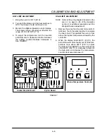
4. To adjust the temperature, turn the lowĆlimit
potentiometer. A clockwise rotation increases
the setting, counterĆclockwise decreases it.
See FIGURE 7.
HIGH LIMIT ADJUSTMENT
NOTE: Refer to the wiring diagram located on the
oven or on page 3-25 of the Operation
section. For additional assistance call the
Blodgett Service department.
1. Remove the wires from the common and N.O.
terminals. Touch the wires together to energize
the heat circuit. This enables the oven to heat
above the highest temperature allowed by the
controller.
2. When the display reads 600
F (316
C), the
burner blower motor should shut off. If the temĆ
perature rises above 600
F (316
C), adjust
the hiĆlimit pot (FIGURE 7) so the burner shuts
off at 600
F (316
C). A clockwise rotation of
the highĆlimit pot increases the temperature,
counterĆclockwise decreases it.
INCREASE
DECREASE
INCREASE
1
2
3
4
5
6
7
8
230 115
NC C NO NO C
DECREASE
LOW LIMIT
HI LIMIT
United Electric Board
Athena Temperature Controller
ZYTRON
SERIES 300
1
3
2
6
5
4
7
8
115
230
NO
C NC
OUTPUT 1
NO C
OUTPUT 2
T1
P1
LOW LIMIT
P2
HI LIMIT
P3
9
10
+
T/C
RED
INCREASE
DECREASE DECREASE
INCREASE
Zytron Board
ACTUAL SETPOINT
HEAT
FIGURE 7
Содержание MT2136 Series
Страница 4: ...INTRODUCTION CHAPTER 1 ...
Страница 15: ...MT2136 1 11 35 30 35 29 39 28 38 33 34 31 37 36 26 27 32 EXTERIOR COMPONENTS FIGURE 3 ...
Страница 17: ...MT2136 1 13 CE GAS BURNER COMPONENTS Control Box not Shown 16 17 FIGURE 5 ...
Страница 18: ...INTRODUCTION 1 14 CONTROL PLATE ASSEMBLY 18 25 16 26 21 19 20 24 23 22 EXCLUSIVE TO CE 40 41 42 43 FIGURE 6 ...
Страница 19: ...MT2136 1 15 This page intentionally left blank ...
Страница 20: ...ASSEMBLY CHAPTER 2 ...
Страница 23: ...MT2136 2 3 This page intentionally left blank ...
Страница 24: ...OPERATION CHAPTER 3 ...
Страница 49: ...MT2136 3 25 16 17 18 19 20 21 12 13 13 13 4 7 15 3 2 1 14 8 9 10 6 11 5 5 FIGURE 4 ...
Страница 50: ...OPERATION 3 26 16 17 20 19 18 15 3 12 13 13 13 4 14 7 1 2 8 9 10 6 11 5 5 FIGURE 5 ...
Страница 51: ...MT2136 3 27 22 23 24 25 26 21 19 18 18 18 4 7 1 3 2 20 5 5 11 12 13 14 15 16 8 17 6 9 10 FIGURE 6 ...
Страница 52: ...OPERATION 3 28 25 26 27 29 28 2 24 23 22 21 21 21 3 1 7 20 4 16 17 18 19 14 15 8 10 6 11 12 13 9 5 5 FIGURE 7 ...
Страница 53: ...MT2136 3 29 1 17 3 2 4 16 16 16 15 21 5 13 14 14 10 18 19 6 7 8 20 9 12 11 FIGURE 8 ...
Страница 54: ...OPERATION 3 30 1 18 16 16 16 16 17 15 22 5 3 2 4 13 10 19 20 6 7 8 21 9 12 11 14 14 FIGURE 9 ...
Страница 55: ...MT2136 3 31 1 21 21 21 17 16 22 18 20 19 14 3 2 4 11 6 13 12 15 10 7 8 9 5 FIGURE 10 ...
Страница 56: ...OPERATION 3 32 1 8 8 8 8 6 7 16 15 17 18 3 2 4 11 5 9 9 12 13 14 FIGURE 11 ...
Страница 57: ...MT2136 3 33 1 6 9 8 19 22 21 7 16 17 2 3 4 18 5 10 14 20 12 11 13 15 25 25 25 24 FIGURE 12 ...
Страница 58: ...OPERATION 3 34 1 FIGURE 13 ...
Страница 60: ...CALIBRATION AND ADJUSTMENT CHAPTER 4 ...
Страница 77: ...MT2136 4 17 This page intentionally left blank ...
Страница 78: ...TROUBLESHOOTING CHAPTER 5 ...
Страница 86: ...TECHNICAL APPENDIX CHAPTER 6 ...


