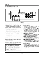
OPERATION
3-4
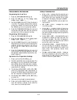
PROGRAMMING PROCEDURES
Programming the Cook Time:
1. Press the PROGRAM/ENTER key (8).
2. Press the TIME key (7). The display reads
PROGĆ?
SET
TIMEĆ?
_ _ _ _.
3. Use the NUMERIC keys (3) to enter the desired
cook time. The display will read the numbers
as they are entered. If an error is made, press
the CLEAR key (4) and reĆenter the number.
4. Press the PROGRAM/ENTER key (8) a second
time to lockĆin the new time. The new cook time
will be stored in the computer's memory.
Programming the Temperature:
1. Press the PROGRAM/ENTER key (8).
2. Press the SET TEMP key (5). The display reads
PROGĆ?
SET
TEMPĆ?
_ _ _ _
F.
3. Use the NUMERIC keys (3) to enter the desired
temperature set point. The control displays the
numbers as they are entered. If an error is
made, press the CLEAR key (4) and reĆenter
the number.
4. Press the PROGRAM/ENTER key (8) a second
time to lockĆin the new temperature. The new
temperature setpoint will be stored in the comĆ
puter's memory.
Operation at the Programmed Settings:
1. Press and hold the ON/OFF key (2).
2. The FAN and HEAT status lamps (9) light. The
fans begin to run. The heat rises to the temperĆ
ature setting stored in the computer's memory.
The conveyor belt begins to travel at the timed
speed stored in memory.
3. The display will flash
WAIT
LOW
SET
TIME
until the programmed bake temperature is
reached. The HEAT lamp (9) will remain lit until
the oven reaches the temperature set point.
4. The display reads
READY
and the HEAT lamp
(9) goes out.
5. The oven is now ready to accept product.
6. Press and hold the ON/OFF key (2) to turn the
oven off. The fans continue to run while the
oven cools to a safe temperature.
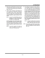
DISPLAY INFORMATION
WAIT
LOW
- indicates that the present oven
temperature is lower than the set point temperĆ
ature. When the oven reaches the set point
temperature the display changes to
READY
.
READY
- indicates that the oven is ready to acĆ
cept product.
SET
TEMP
mmss
- indicates the current
cook time setting.
HIGH
TIME
- indicates that the temperature
is well above the set point. This usually occurs
when moving from a higher āto a lower temperaĆ
ture. Wait until the display reads ready before
loading product.
HIGH
TEMP
LIMIT
- indicates that the oven
temperature exceeds the high limit from the
2nd level program. The Over Temperature
Alarm buzzer will sound. Shut the oven off and
wait for the unit to cool down.
HIGH
TEMP
PANEL
- indicates that the conĆ
trol area reaches an excessive temperature.
Shut the oven off and wait for the unit to cool
down. Error code generally means loose
ground wire.
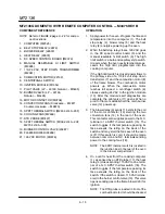
PROBE
OPEN
PROBE
SHORT
- indicates
that the temperature sensor has failed. The
Alarm buzzer sounds. Shut the oven off and
contact a service representative.
Содержание MT2136 Series
Страница 4: ...INTRODUCTION CHAPTER 1 ...
Страница 15: ...MT2136 1 11 35 30 35 29 39 28 38 33 34 31 37 36 26 27 32 EXTERIOR COMPONENTS FIGURE 3 ...
Страница 17: ...MT2136 1 13 CE GAS BURNER COMPONENTS Control Box not Shown 16 17 FIGURE 5 ...
Страница 18: ...INTRODUCTION 1 14 CONTROL PLATE ASSEMBLY 18 25 16 26 21 19 20 24 23 22 EXCLUSIVE TO CE 40 41 42 43 FIGURE 6 ...
Страница 19: ...MT2136 1 15 This page intentionally left blank ...
Страница 20: ...ASSEMBLY CHAPTER 2 ...
Страница 23: ...MT2136 2 3 This page intentionally left blank ...
Страница 24: ...OPERATION CHAPTER 3 ...
Страница 49: ...MT2136 3 25 16 17 18 19 20 21 12 13 13 13 4 7 15 3 2 1 14 8 9 10 6 11 5 5 FIGURE 4 ...
Страница 50: ...OPERATION 3 26 16 17 20 19 18 15 3 12 13 13 13 4 14 7 1 2 8 9 10 6 11 5 5 FIGURE 5 ...
Страница 51: ...MT2136 3 27 22 23 24 25 26 21 19 18 18 18 4 7 1 3 2 20 5 5 11 12 13 14 15 16 8 17 6 9 10 FIGURE 6 ...
Страница 52: ...OPERATION 3 28 25 26 27 29 28 2 24 23 22 21 21 21 3 1 7 20 4 16 17 18 19 14 15 8 10 6 11 12 13 9 5 5 FIGURE 7 ...
Страница 53: ...MT2136 3 29 1 17 3 2 4 16 16 16 15 21 5 13 14 14 10 18 19 6 7 8 20 9 12 11 FIGURE 8 ...
Страница 54: ...OPERATION 3 30 1 18 16 16 16 16 17 15 22 5 3 2 4 13 10 19 20 6 7 8 21 9 12 11 14 14 FIGURE 9 ...
Страница 55: ...MT2136 3 31 1 21 21 21 17 16 22 18 20 19 14 3 2 4 11 6 13 12 15 10 7 8 9 5 FIGURE 10 ...
Страница 56: ...OPERATION 3 32 1 8 8 8 8 6 7 16 15 17 18 3 2 4 11 5 9 9 12 13 14 FIGURE 11 ...
Страница 57: ...MT2136 3 33 1 6 9 8 19 22 21 7 16 17 2 3 4 18 5 10 14 20 12 11 13 15 25 25 25 24 FIGURE 12 ...
Страница 58: ...OPERATION 3 34 1 FIGURE 13 ...
Страница 60: ...CALIBRATION AND ADJUSTMENT CHAPTER 4 ...
Страница 77: ...MT2136 4 17 This page intentionally left blank ...
Страница 78: ...TROUBLESHOOTING CHAPTER 5 ...
Страница 86: ...TECHNICAL APPENDIX CHAPTER 6 ...


