OPERATION
3-18
closes when there is a 10Ć20
5
drop in
temperature across the face of the
switch.
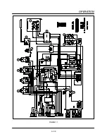
4. On a call for heat from the cooking computer
(1), as sensed by an RTD probe (18), the heat
relay (4) closes sending 24 VAC to the burner
control valve (13). This valve opens sending
gas to the flame blower for ignition.
NOTE: The RTD probe is located in front of the
combustion motor. It should be checked
with an ohm meter.
5. The conveyor belt is driven by a closed loop
D.C. drive system consisting of a 130 VDC moĆ
tor (19), a #2 Hall effect pickup (20), a DC
speed control board (5) and the DAC located
in the cooking computer. The motor speed varĆ
ies based on the time programmed into the
cooking computer. If time is programmed, a
voltage from .3 to 3.8 is applied to the DC
speed control board. The output voltage meaĆ
sured at terminals A1 and A2 varies from 20 to
130 VDC based on the DAC voltage applied to
the board or the time programmed into the
computer.
NOTE: The DAC receives 20 VDC from the
speed control board. The DAC returns
a portion of the voltage (between .3
and 3.8 VDC). The amount of voltage is
dependent on the time programmed
into the computer.
NOTE: This type of system does sense the
weight of the product and will not slow
down if the belt is fully loaded.
NOTE: The control voltage is supplied by a
240/120 step down transformer (8).
The transformer is located in the conĆ
trol compartment.
6. There are two cooling fans (21) located in the
rear convection fan compartment and one loĆ
cated in the control compartment. These fans
are activated when the belt stop relay (2) is enĆ
ergized. The fans are also activated when a
SPDT thermal switch (22) toggles from comĆ
mon/NC to common NO. The switch toggles
due to high ambient heat. It will toggle if the
temperature passing its face exceeds the ratĆ
ing on the back of the switch.
NOTE: The switch is located between the two
blowers in the rear convection fan
compartment. It protects the convecĆ
tion fans from hi ambient heat.
Содержание MT2136 Series
Страница 4: ...INTRODUCTION CHAPTER 1 ...
Страница 15: ...MT2136 1 11 35 30 35 29 39 28 38 33 34 31 37 36 26 27 32 EXTERIOR COMPONENTS FIGURE 3 ...
Страница 17: ...MT2136 1 13 CE GAS BURNER COMPONENTS Control Box not Shown 16 17 FIGURE 5 ...
Страница 18: ...INTRODUCTION 1 14 CONTROL PLATE ASSEMBLY 18 25 16 26 21 19 20 24 23 22 EXCLUSIVE TO CE 40 41 42 43 FIGURE 6 ...
Страница 19: ...MT2136 1 15 This page intentionally left blank ...
Страница 20: ...ASSEMBLY CHAPTER 2 ...
Страница 23: ...MT2136 2 3 This page intentionally left blank ...
Страница 24: ...OPERATION CHAPTER 3 ...
Страница 49: ...MT2136 3 25 16 17 18 19 20 21 12 13 13 13 4 7 15 3 2 1 14 8 9 10 6 11 5 5 FIGURE 4 ...
Страница 50: ...OPERATION 3 26 16 17 20 19 18 15 3 12 13 13 13 4 14 7 1 2 8 9 10 6 11 5 5 FIGURE 5 ...
Страница 51: ...MT2136 3 27 22 23 24 25 26 21 19 18 18 18 4 7 1 3 2 20 5 5 11 12 13 14 15 16 8 17 6 9 10 FIGURE 6 ...
Страница 52: ...OPERATION 3 28 25 26 27 29 28 2 24 23 22 21 21 21 3 1 7 20 4 16 17 18 19 14 15 8 10 6 11 12 13 9 5 5 FIGURE 7 ...
Страница 53: ...MT2136 3 29 1 17 3 2 4 16 16 16 15 21 5 13 14 14 10 18 19 6 7 8 20 9 12 11 FIGURE 8 ...
Страница 54: ...OPERATION 3 30 1 18 16 16 16 16 17 15 22 5 3 2 4 13 10 19 20 6 7 8 21 9 12 11 14 14 FIGURE 9 ...
Страница 55: ...MT2136 3 31 1 21 21 21 17 16 22 18 20 19 14 3 2 4 11 6 13 12 15 10 7 8 9 5 FIGURE 10 ...
Страница 56: ...OPERATION 3 32 1 8 8 8 8 6 7 16 15 17 18 3 2 4 11 5 9 9 12 13 14 FIGURE 11 ...
Страница 57: ...MT2136 3 33 1 6 9 8 19 22 21 7 16 17 2 3 4 18 5 10 14 20 12 11 13 15 25 25 25 24 FIGURE 12 ...
Страница 58: ...OPERATION 3 34 1 FIGURE 13 ...
Страница 60: ...CALIBRATION AND ADJUSTMENT CHAPTER 4 ...
Страница 77: ...MT2136 4 17 This page intentionally left blank ...
Страница 78: ...TROUBLESHOOTING CHAPTER 5 ...
Страница 86: ...TECHNICAL APPENDIX CHAPTER 6 ...

