MT2136
4-5
TEMPERATURE CALIBRATION - ATHENA CONTROLLER
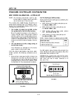
THE CONFIGURATION MENUS
1. Press and hold the actual temperature key for
approximately 10 seconds. When the menu
system has been accessed, the display
toggles between and either or .
Setting the Default Display
The default display determines whether the controlĆ
ler displays the actual or the setpoint temperature.
1. Use the arrow keys to select the desired disĆ
play default.
NOTE: We recommend using the setpoint disĆ
play default.
2. Press the actual temperature key to enter the
selected display default. The display will
toggle between and a numerical value.
Setting the Control Hysteresis
The control hysteresis, or the burner cycle is used
to prevent rapid cycling around the setpoint. The
hysteresis is adjustable from 2
F to 252
F (0
C to
140
C).
1. Use the arrow keys to select the desired conĆ
trol hysteresis.
NOTE: We recommend using 5
F initially.
2. Press the actual temperature key to enter the
selected hysteresis value. The display will
toggle between and a numerical value.
Setting the Display Offset
The display offset is used to provide a limited adĆ
justment of the displayed temperature as a comĆ
pensation for offsets between the actual temperaĆ
ture and the temperature seen by the
thermocouple. The display offset is adjustable
from Ć126
F to +126
F (Ć70
C to 70
C).
1. Use the arrow keys to select the desired disĆ
play offset.
2. Press the actual temperature key to enter the
selected offset value. The display will toggle
between and a numerical value.
Setting the Deviation Band Alarm
The deviation band alarm causes the display to
flash when the actual temperature varies (in either
direction) from the setpoint. The deviation band
alarm is adjustable to off or values from 1
F to
252
F (1
C to 740
C).
1. Use the arrow keys to select the desired deviĆ
ation band alarm.
2. Press the actual temperature key to enter the
selected alarm value.
To exit the Configuration Menus
1. Push and hold the actual temperature key for
approximately 3 seconds.
NOTE: The unit exits the configuration menus if the
controller is not touched for 1 minute at any
time during the programming process.
SETTING THE DISPLAY UNITS
NOTE: On newer models, skip steps 1Ć3.
1. Disconnect the power from the control. ReĆ
move all wires and the back of the control.
2. Locate the black jumper on the microcontroller
board next to the thermocouple connection.
Install the jumper on both pins.
3. Reconnect the power to the control.
4. Press and hold the actual temperature key for
approximately 10 seconds until the display
reads
and flashes or . Press the up or
down arrow key to toggle between
F and
C.
5. Press and hold the actual temperature key unĆ
til the control exits the programming mode.
NOTE: DO NOT disconnect power and move the
jumper back to single pin until the control
has returned to normal operation.
Содержание MT2136 Series
Страница 4: ...INTRODUCTION CHAPTER 1 ...
Страница 15: ...MT2136 1 11 35 30 35 29 39 28 38 33 34 31 37 36 26 27 32 EXTERIOR COMPONENTS FIGURE 3 ...
Страница 17: ...MT2136 1 13 CE GAS BURNER COMPONENTS Control Box not Shown 16 17 FIGURE 5 ...
Страница 18: ...INTRODUCTION 1 14 CONTROL PLATE ASSEMBLY 18 25 16 26 21 19 20 24 23 22 EXCLUSIVE TO CE 40 41 42 43 FIGURE 6 ...
Страница 19: ...MT2136 1 15 This page intentionally left blank ...
Страница 20: ...ASSEMBLY CHAPTER 2 ...
Страница 23: ...MT2136 2 3 This page intentionally left blank ...
Страница 24: ...OPERATION CHAPTER 3 ...
Страница 49: ...MT2136 3 25 16 17 18 19 20 21 12 13 13 13 4 7 15 3 2 1 14 8 9 10 6 11 5 5 FIGURE 4 ...
Страница 50: ...OPERATION 3 26 16 17 20 19 18 15 3 12 13 13 13 4 14 7 1 2 8 9 10 6 11 5 5 FIGURE 5 ...
Страница 51: ...MT2136 3 27 22 23 24 25 26 21 19 18 18 18 4 7 1 3 2 20 5 5 11 12 13 14 15 16 8 17 6 9 10 FIGURE 6 ...
Страница 52: ...OPERATION 3 28 25 26 27 29 28 2 24 23 22 21 21 21 3 1 7 20 4 16 17 18 19 14 15 8 10 6 11 12 13 9 5 5 FIGURE 7 ...
Страница 53: ...MT2136 3 29 1 17 3 2 4 16 16 16 15 21 5 13 14 14 10 18 19 6 7 8 20 9 12 11 FIGURE 8 ...
Страница 54: ...OPERATION 3 30 1 18 16 16 16 16 17 15 22 5 3 2 4 13 10 19 20 6 7 8 21 9 12 11 14 14 FIGURE 9 ...
Страница 55: ...MT2136 3 31 1 21 21 21 17 16 22 18 20 19 14 3 2 4 11 6 13 12 15 10 7 8 9 5 FIGURE 10 ...
Страница 56: ...OPERATION 3 32 1 8 8 8 8 6 7 16 15 17 18 3 2 4 11 5 9 9 12 13 14 FIGURE 11 ...
Страница 57: ...MT2136 3 33 1 6 9 8 19 22 21 7 16 17 2 3 4 18 5 10 14 20 12 11 13 15 25 25 25 24 FIGURE 12 ...
Страница 58: ...OPERATION 3 34 1 FIGURE 13 ...
Страница 60: ...CALIBRATION AND ADJUSTMENT CHAPTER 4 ...
Страница 77: ...MT2136 4 17 This page intentionally left blank ...
Страница 78: ...TROUBLESHOOTING CHAPTER 5 ...
Страница 86: ...TECHNICAL APPENDIX CHAPTER 6 ...


