MT2136
3-3
COMPUTER CONTROLLER
1
2
3
4
5
6
7
8
9
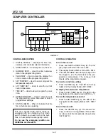
FIGURE 3
CONTROL DESCRIPTION
1. DIGITAL DISPLAY - Displays the time, temĆ
perature and controller related information.
2. OVEN ON/OFF - Controls power to the oven.
3. NUMERIC KEYS - Used to enter numerical
data in the programming mode.
4. CLEAR KEY - Used to clear the display if an
error is made in the programming mode.
5. SET TEMP KEY - Used to view or program the
temperature setpoint.
6. ACT TEMP KEY - Used to view the current
oven temperature.
7. TIME KEY - Used to view or program the cook
time.
8. PROG/ENTER KEY - Used to enter and exit
the programming mode. Also used to lock in
programmed settings.
9. STATUS LAMPS - When lit indicate that the
fan or burners are operating.
This oven, supplied with remote control, is
equipped with an emergency shut down
switch. Should you need to stop the belt,
fans, or heat press the emergency switch.
Do not use the emergency switch as a
GENERAL on/off switch!
CONTROL OPERATION
To turn the oven on:
1. Press and hold the ON/OFF key (2). The disĆ
play reads
OFF
when the oven is idle.
2. The display flashes
WAIT
LOW
SET
TIME.
3. The FAN and HEAT status lamps (9) light. The
fans begin to run. The heat rises to the proĆ
grammed temperature. The conveyor belt
travels at the programmed speed.
To view the cook time setting:
1. Press the TIME key (7). The LED on the key
lights and the display flashes
SET
TIME.
To display the actual oven temperature:
1. Press the ACT TEMP key (6). The LED on the
key lights and the display reads
ACTUAL
F.
To view the temperature set point:
1. Press the SET TEMP key (5). The LED on the
key lights and the display flashes
SET
TEMP
F.
To turn the oven off:
1. Press the ON/OFF key (2). The blower moĆ
tor(s) continue to run regardless of the controlĆ
ler status until the temperature drops below
180
F (82
C).
Содержание MT2136 Series
Страница 4: ...INTRODUCTION CHAPTER 1 ...
Страница 15: ...MT2136 1 11 35 30 35 29 39 28 38 33 34 31 37 36 26 27 32 EXTERIOR COMPONENTS FIGURE 3 ...
Страница 17: ...MT2136 1 13 CE GAS BURNER COMPONENTS Control Box not Shown 16 17 FIGURE 5 ...
Страница 18: ...INTRODUCTION 1 14 CONTROL PLATE ASSEMBLY 18 25 16 26 21 19 20 24 23 22 EXCLUSIVE TO CE 40 41 42 43 FIGURE 6 ...
Страница 19: ...MT2136 1 15 This page intentionally left blank ...
Страница 20: ...ASSEMBLY CHAPTER 2 ...
Страница 23: ...MT2136 2 3 This page intentionally left blank ...
Страница 24: ...OPERATION CHAPTER 3 ...
Страница 49: ...MT2136 3 25 16 17 18 19 20 21 12 13 13 13 4 7 15 3 2 1 14 8 9 10 6 11 5 5 FIGURE 4 ...
Страница 50: ...OPERATION 3 26 16 17 20 19 18 15 3 12 13 13 13 4 14 7 1 2 8 9 10 6 11 5 5 FIGURE 5 ...
Страница 51: ...MT2136 3 27 22 23 24 25 26 21 19 18 18 18 4 7 1 3 2 20 5 5 11 12 13 14 15 16 8 17 6 9 10 FIGURE 6 ...
Страница 52: ...OPERATION 3 28 25 26 27 29 28 2 24 23 22 21 21 21 3 1 7 20 4 16 17 18 19 14 15 8 10 6 11 12 13 9 5 5 FIGURE 7 ...
Страница 53: ...MT2136 3 29 1 17 3 2 4 16 16 16 15 21 5 13 14 14 10 18 19 6 7 8 20 9 12 11 FIGURE 8 ...
Страница 54: ...OPERATION 3 30 1 18 16 16 16 16 17 15 22 5 3 2 4 13 10 19 20 6 7 8 21 9 12 11 14 14 FIGURE 9 ...
Страница 55: ...MT2136 3 31 1 21 21 21 17 16 22 18 20 19 14 3 2 4 11 6 13 12 15 10 7 8 9 5 FIGURE 10 ...
Страница 56: ...OPERATION 3 32 1 8 8 8 8 6 7 16 15 17 18 3 2 4 11 5 9 9 12 13 14 FIGURE 11 ...
Страница 57: ...MT2136 3 33 1 6 9 8 19 22 21 7 16 17 2 3 4 18 5 10 14 20 12 11 13 15 25 25 25 24 FIGURE 12 ...
Страница 58: ...OPERATION 3 34 1 FIGURE 13 ...
Страница 60: ...CALIBRATION AND ADJUSTMENT CHAPTER 4 ...
Страница 77: ...MT2136 4 17 This page intentionally left blank ...
Страница 78: ...TROUBLESHOOTING CHAPTER 5 ...
Страница 86: ...TECHNICAL APPENDIX CHAPTER 6 ...


