background image

Troubleshooting 

bkSpecto Ultrasound System 


4-82 

SM41406-4 


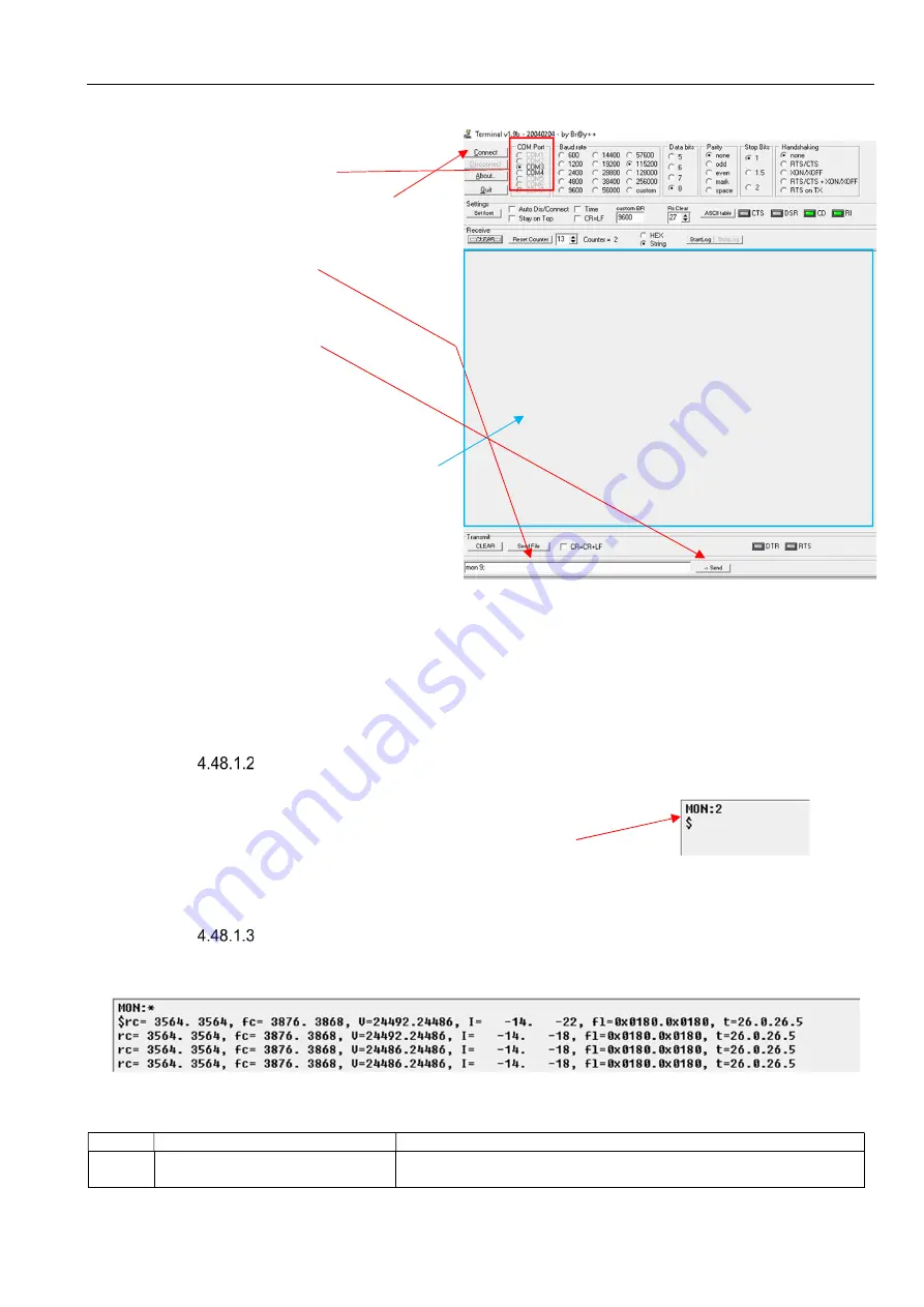
2.  Doubleclick on Terminal icon on the desktop 

3.  Make sure all settings are as 

depicted below. The COM Port 
can be different 

4.  Click on Connect Button  
 
 
5.  Type 

mon 9;


6.  click on 

Send


7.  Once done monitoring you can 

copy paste all content from this 
data output area to a Notepad 
text document 


8.  Type 

mon 2;

 and click on 

Send

 (this is the default state) 

 
Caution: 

Do not start the console application while being in 

mon 9

 state. Remember to switch back to 

mon 2

 state before starting the console  application.  

 
Caution:  

If you are in 

mon 9

 state and you restart the terminal application, the system will still be in 

mon 9

 state. 


  Read monitoring state 

 
1.  Type 

mon;

 and click on 

Send


2.  Read in Data output area the monitoring state. 

(In this example the monitoring state is 2) 


  Read data output 

 
Below is an example of the data that you see when you are in monitoring state 9. 

 
All values are written as pairs as there are always 2 batteries. 


Value 

Text 

Comment 

rc 

Actual electrical charge 
measured in mAh 


Data output area 

Содержание bkSpecto 1300

Страница 1: ...Service Manual Diagnostic Ultrasound System 1300 bkSpecto...

Страница 2: ......

Страница 3: ...General Information 2 Service Notes 3 Checking Procedure 4 Trouble Shooting Guides 5 Adjustment Procedure 6 Mechanical Parts 7 Preventative Maintenance 8 Theory of Operation 9 System Interconnections...

Страница 4: ......

Страница 5: ...1 4 System Overview 1 4 1 5 System Configuration 1 4 Scanner Serial Number 1 5 1 6 Exploded Views and Part Lists 1 5 Engine 1 5 Keyboard 1 7 Top Assy 1 8 Monitor 1 9 Monitor arm 1 9 Wheelbase 1 9 1 7...

Страница 6: ...cription ATTENTION Consult ACCOMPANYING User Guide when this sign is encountered on the instrument to avoid reducing its safety Potential Equalisation Terminal connected to the chassis Should be conne...

Страница 7: ...d or repaired by other parties After service or repairs have been carried out a qualified electrician or hospital technician should verify the safety of all equipment Personal Safety Be aware that the...

Страница 8: ...ies are available such as baskets foot switch printer start up kit and extra holders Table 1 1 contains an overview of the bkSpecto modelversions Figure 1 1 bkSpecto system overview Model Version Vers...

Страница 9: ...about Ref type number 1 scanner specific serial number 2 model number 3 and production date 4 Figure 1 2 Scanner Specific Serial Number Label 1 6 Exploded Views and Part Lists Engine Item Reference De...

Страница 10: ...r Board J32 IO Board HDMI 21 05491 01 109 6 81250 01 Engine Hinge Pin 6 81250 01 110 Standby Button Base Kit 6 81714 01S 111 10 78039 01 Control Cable Callisto Main Board Charger board J6 10 78039 01...

Страница 11: ...5659 01 GPU 21 05659 01 119 10 78841 01 Battery Power Switch Assy Power switch Charger Board J35 10 78841 01 Keyboard Item Reference Description Spare Part Image 201 21 05264 01 Touch Keyboard 21 0526...

Страница 12: ...mage 301 6 79697 01 Right cover 6 79697 01S 302 6 81407 01 Left cover 6 81407 01S 303 6 81251 01 Rear cover 6 81251 01 304 10 78270 01 Complete Engine with battery 10 78270 01S 10 78270 05 Complete En...

Страница 13: ...ard LCD Panel 21 05514 01 406 10 79679 01 Power Cable Display Controller Board Standby button board 10 79679 01 407 10 78131 01 Power Cable Display Controller Board Sensor board 10 78131 01 408 6 8171...

Страница 14: ...Z9051 Cup for holder DZ9051 607 6 81194 01 Probe Holder Green 6 81194 01 608 6 80994 01 Gel Bottle Holder Cup 6 80994 01 609 6 80995 01 Gel Bottle Holder Green 6 80995 01 610 6 82609 01 Bottle Base 6...

Страница 15: ...able Display Controller Board Sensor board 10 78131 01 10 78131 01 14a USB Cable Charger Board IO Board 21 05491 01 21 05491 01 14b HDMI Cable Charger Board IO Board 21 05497 03 21 05497 03 15a Power...

Страница 16: ...ine Out 6 Microphone In 7 Used for production and research purposes 1 9 Ground Protection Item Symbol Description Location 1 Potential Equalisation Below the engine in front of the power inlet 1 10 Sp...

Страница 17: ...nded tools are Static control service kit Torx keys 10 and 15 Small slot screwdriver to remove the screw covers hiding the screws on the engine 6 81516 01 and on the monitor Spare screw covers 6 81516...

Страница 18: ...General Information bkSpecto Ultrasound System 1 14 SM41406 4 This page is intentionally left blank...

Страница 19: ...bkSpecto Ultrasound System Service Notes SM41406 4 2 1 Section 2 Service Notes CONTENTS PAGE 2 Service Notes 2 2 2 1 Edition Number 2 2...

Страница 20: ...s to this Service Manual will be released as Service Hotlines and posted to the BK Ultrasound Service Web A user name and password are required to access BK Ultrasound Service Web Register on web bkme...

Страница 21: ...System Checking Procedure SM41406 4 3 1 Section 3 Checking Procedure CONTENTS PAGE 3 Checking the system after repair 3 2 3 1 Getting Started Guides 3 2 3 2 Guides 3 2 3 3 Required Equipment 3 2 3 4...

Страница 22: ...s a specific system fault refer to Section 4 Troubleshooting in this Service Manual The Getting Started Guides do not include transducer checks Consult the relevant User Guide or Getting Started Guide...

Страница 23: ...age 4 12 Program Foot Pedal 4 13 Video Output 4 13 Changing Measurement Results 4 14 Changing Calculation List 4 14 Changing Labels 4 15 Configure Layout for the Parameter Buttons 4 16 Access the User...

Страница 24: ...ooting 4 38 Testing Errors 4 38 DICOM Status 4 39 Ping 4 42 Printers 4 43 Setting Up a Sony Printer 4 43 Setting Up an Office Printer 4 43 Crash Recoveries 4 43 Log Files 4 43 Export Log Files 4 43 Ho...

Страница 25: ...4 68 Run ChkDsk 4 69 3rd Part Software on the Scanner 4 70 Installing Software Updates 4 70 Downloading New Software 4 70 Installing New Software 4 71 Activate Windows 4 71 BIOS 4 73 Accessing BIOS is...

Страница 26: ...monitoring state 4 82 Read data output 4 82 Read Cycle count and serial number 4 83 Configure a Scanner to Archive to a Network Drive SW 6 6 4 and after 4 83 Conforming Microsoft Windows based PC Stat...

Страница 27: ...the hazards involved Any internal repairs performed on the system must be followed by an Electrical Safety Test section 7 and document number 16 01491 Caution As the boards in the system are sensitiv...

Страница 28: ...license based functionalities such as presets support of transducers etc Check the Windows time is correct If the Windows time is wrong it could be due to a discharged BIOS battery If the clock has be...

Страница 29: ...on Color Doppler 2D Turn on 2D imaging Double tap the 2D button to exit all modes and return to 2D mode only Home Tab the Home button to return to default settings for the current exam type TGC Displ...

Страница 30: ...ncluding the sub options Option Sub Options System Header Display Patient Data MISC Presets Available Default Manage Measure Calc General Calc List Results Preferences Labeling Labels Bodymarks Needle...

Страница 31: ...nge Time Format and Date Format 1 Tap on the Setup button 2 Tap on SYSTEM 3 Choose the relevant date format 4 Choose the relevant time format 5 Finish by UPDATE TIME Change Time 1 Tap on the Setup but...

Страница 32: ...n the lower right corner 3 Click on Change date and time settings 4 Click on Change time zone 5 Select the relevant time zone on the drop down list and press OK Enable or disable Daylight settings 6 C...

Страница 33: ...omize Patient Data Entries 1 Ensure the scanner is in Console mode 2 Tap on the Tools button 3 Tap on SYSTEM 4 Go to the PATIENT DATA tab 5 To ADD patient data entries drag the parameters from the lef...

Страница 34: ...g bkSpecto Ultrasound System 4 12 SM41406 4 Change Language 1 Ensure the scanner is in Console mode 2 Tap on the Tools button 3 Tap on SYSTEM 4 Go to the MISC tab 5 Select the relevant language 6 Rebo...

Страница 35: ...administrator 2 Tap on the Tools button 3 Click on SYSTEM 4 Go to the MISC tab 5 Select the relevant foot pedal and function on the list Video Output 1 Ensure the scanner is in Console mode 2 Tap on...

Страница 36: ...l monitor modes Note The external monitor must support the relevant resolution defined in Table 4 3 If this is not the case the monitor will not be detected by the Console Changing Measurement Results...

Страница 37: ...7 To remove calculations a Select the button which should be remove b Select Remove Changing Labels 1 Tap on the Tools button 2 Tap on LABELING 3 Tap on LABELS 4 Select relevant pro package from the...

Страница 38: ...abels a Select the label which should be removed b Tap on the Remove button Configure Layout for the Parameter Buttons The touch functionality allows to customize the user layout Figure 4 3 Drag butto...

Страница 39: ...e User Guide The User Guide is available on the scanner as a HTML format 1 Ensure the system is in Console mode 2 Click on the Current User drop down menu 3 Select Help 4 The User Manual will show on...

Страница 40: ...me Free HDD space Scanner Variant Engine software version Console software version Flexiblekeyboard software version XPE version License ID 00 00 0 followed by scanner SN MAC Address Hardware Capabili...

Страница 41: ...ed before it can be used for scanning again Table 4 5 contains an error dialog and explanation of the buttons Message Dialog Error dialog A Type of warning B Reason for warning C Standard message numb...

Страница 42: ...ing the Service mode button ref 4 18 1 or using an external keyboard ref 4 18 2 CAUTION Always leave the scanner after technical service in Console mode Only BK Ultrasound certified staff is allowed t...

Страница 43: ...where this procedure does not work it is possible to boot from a bootable device This is described in section 4 26 Entering Console Mode 13 On the Service Desktop select Console mode 14 When the term...

Страница 44: ...hen the scanner will shut down Restarting the Scanner from Service mode 1 On the Service Desktop double click the Restart Scanner icon Search Functionality in Windows 1 Access Service mode 4 18 1 2 Pr...

Страница 45: ...ion if relevant 10 78270 01S Spare engine Disable encryption if relevant Reprogram the serial number Restore user settings patient database license key s computer name and activate windows Table 4 7 R...

Страница 46: ...rmance using section 3 Checking Procedure 10 Make sure the sure the system configuration is updated on the BK Ultrasound Service Web Reprogramming the Serial Number To Reprogram the Serial Number afte...

Страница 47: ...tional Data field already contains a number write it down in the event of a rollback is necessary 11 In the Additional Data field enter the code obtained from BK Ultrasound and press Write 12 Select X...

Страница 48: ...n the monitor Additional is a power switch located on the engine next to the power inlet The location and function of the power buttons can be found in Table 4 8 Power Button Location Functionality En...

Страница 49: ...RS HIPAA Login in Console Mode 1 Ensure the scanner boots in Console mode 2 Choose the relevant user on the touch screen 3 If this user is protected by a password submit the password using the input r...

Страница 50: ...Sys Admin and Default User The passwords are available in chapter 4 28 It is possible to create additional users and administrator with customizable settings and preferences Add a User 1 Login as the...

Страница 51: ...user settings and preferences Remove a User 1 Ensure the scanner is in Console mode and logged in as an administrator 2 Tap on Tools button 3 Tap on SECURITY 4 Tap on relevant user profile 5 Tap on D...

Страница 52: ...9 and Table 4 10 General User Settings A Add user photo B Change Password C Profile type D Password mandatory E Allow user to modify user preferences F User specific preferences ref Table 4 10 Table 4...

Страница 53: ...User NA Password Pasword Note If the default administrator password is changed and forgotten then contact your local BK Medical technical support DICOM Before attempting to configure DICOM ask the in...

Страница 54: ...he scanner 3 Select Apply 4 To define a fixed IP address continue If left at the default setting the scanner will obtain an IP address from the network s DHCP server 5 Select Configure Network and typ...

Страница 55: ...he institution IP address Subnet mask Default gateway 12 Select OK until all windows are closed 13 Close the Network Connections window Worklist Setup Note Scanner AE Title must be present before test...

Страница 56: ...rklist All Systems No filtering All modalities on the worklist will appear on the scanner Table 4 11 Search filter possibilities when setting up a worklist To Configure the DICOM Worklist 1 Access the...

Страница 57: ...a new exam will also auto archive images and clips for the previous patient This is the default Archiving Method Table 4 12 Available archiving method options for PACS Method Definition Send complete...

Страница 58: ...PACS drop down menu select the desired setting Note Each time a new PACS server is added it will automatically become the default Select from the following options No to ensure the new PACS server is...

Страница 59: ...s and Port Number Note Once accepted Name cannot be edited 8 Select Test 9 Select OK twice DICOM Printers Setup Note Scanner AE Title must be present before testing can be done To Configure Printers 1...

Страница 60: ...r 7 Scanner will ping target host 8 Scanner will send out a DICOM echo to target host If the first part fails you may get a message like this Check the following items to ensure they are correctly con...

Страница 61: ...have three different colors as defined in Table 4 15 LED Color Definition Green Everything is OK Image transfer was successful The button will disappear Yellow Transfer is underway Red Transfer failed...

Страница 62: ...trasound System 4 40 SM41406 4 3 The DICOM Status dialog will be presented To Delete Documents in the DICOM Queue 1 Access the DICOM Setting Dialog according to 4 29 1 2 Select Status 3 The DICOM Stat...

Страница 63: ...r the entire list 5 Select Yes to confirm the deletion or No to cancel it To Test Failed DICOM Server Printer 1 Access the DICOM Setting Dialog according to 4 29 1 2 Select Status 3 The DICOM Status d...

Страница 64: ...m the Device List and select Details Ping To Ping a DICOM Server 1 Access the DICOM Setting Dialog according to 4 29 1 2 Select Ping 3 Enter a target IP Address Note If the network includes a DNS Doma...

Страница 65: ...an Office Printer This is covered in the User Guide available on the BK Ultrasound webpage Crash Recoveries TBA Log Files Log files and a fault description are often necessary for remote support by yo...

Страница 66: ...contains Information Warning Error SysEvent evt Windows system event view contains Information Warning Error HWM_log txt Logs from the hard ware monitor LogExtension_YYYYDDMM_HHMMSS log When an error...

Страница 67: ...e screen by pressing CTRL ESC 3 Write cmd 4 Open the command prompt 5 Write ipconfig and press enter 6 Under the relevant connection the IP address is written as the IPv4 Address Enable Static IP Addr...

Страница 68: ...6 Select Advanced Wi Fi Setup 7 Submit the password ref chapter 4 28 8 Double click on Wi Fi or Ethernet 9 If Wi Fi was chosen press Properties If Ethernet was chosen continue to next step 10 Select...

Страница 69: ...per default disabled on the scanner Enable inbound PING functionality Automatically 1 Ensure the scanner is in Service mode 2 Open the Tools folder on the desktop 3 Open the folder called USfiles 4 R...

Страница 70: ...r Inbound Rules 12 Find the File and Printer Sharing Echo Request ICMPv4 In rule in the Inbound Rules list 13 Right click on the File and Printer Sharing Echo Request ICMPv4 In and select Enable rule...

Страница 71: ...mode 2 Tap on Tools button 3 Tap on STORE NETWORK 4 Tap on the Wi Fi tab 5 Tap on CONFIGURE Wi Fi 6 Tap on the relevant network and press Connect 7 Submit the password and press OK 8 Close the network...

Страница 72: ...way to do it 802 1x authentication is a method which can be used to ensure the scanner is connected to the correct access point The authentication is obtained by certificates which are used to tell t...

Страница 73: ...g Password protected certificate with personal key for Personal as a PFX file including the password Root certificate from issuing certificate servers for Trusted Root Certification Authorities Insert...

Страница 74: ...Troubleshooting bkSpecto Ultrasound System 4 52 SM41406 4 4 Press Add 5 Select Computer account and press Next 6 Press Finish...

Страница 75: ...added to the snap ins Press OK 8 Open Certificate Local Computer 9 Right click Personal Select All Tasks Import from the options 10 Use the Certificate Import Wizard to select the PFX certificate fil...

Страница 76: ...ities Select All Tasks Import 12 Use the Certificate Import Wizard to select the certificate file obtained from the local IT department for Trusted Root Certification Authorities Follow the import gui...

Страница 77: ...urce Go to 0 Error Reference source not found The certificate is issued by a trusted source Continue this guide 16 Open the Certification Path tab 17 Note the certification path for later usage Create...

Страница 78: ...19 Select Set up a new connection or network 20 Select Manually connect to a wireless network Press Next 21 Enter the SSID network name of the wireless network and select WPA2 Enterprise security 22...

Страница 79: ...the Security tab and choose Microsoft Smart Card or other Certificate as authentication method 25 Click Settings 26 Ensure Verify the server s identity by validating the certificate is enabled 10 Cho...

Страница 80: ...er authentication from the dropdown menu 13 Click OK and Click OK again on the next screen 14 Press the Wireless icon on the taskbar 15 Choose the created network and press Connect 16 Press Console Mo...

Страница 81: ...ource is not trusted 3 The identity certificate for the source must be obtained from the IT department and imported to Trusted Root Certification Authorities as described in the previous procedure 4 I...

Страница 82: ...ode 2 Plug in a USB keyboard 3 Select the Windows button on the keyboard and search for cmd 4 Right click on the button and select run as administrator 5 Type netsh wlan delete profile and press Enter...

Страница 83: ...bkSpecto Ultrasound System Troubleshooting SM41406 4 4 61 9 Select Network and Sharing Center 10 Select Set up a new connection or network 11 Select Manually connect to a wireless network...

Страница 84: ...06 4 12 Complete the form with all relevant details 13 Select Next 14 When presented with successful installation window select Close 15 On the Service Desktop double click on the desktop icon Console...

Страница 85: ...partitions Figure 4 5 The three partitions on the SSD must be named C Q and S E F and G are being used for USB connections Drive letters and function for each drive are described in Table 4 17 Figure...

Страница 86: ...for clips ref 4 40 2 2 Config Console configuration files Console ini Initializing file for Console Application Console exe Console application DICOM DICOM program files DICOM log DICOM logfile DICOM...

Страница 87: ...up Database The main database is named bk1500 mdb and contains most system setup data and all transducer pro package setup data There are also a variety of mdb backup files for example bk1500_backup_y...

Страница 88: ...ING 3 Log warning errors and fatal errors Default LOG_LEVEL_INFO 4 Log information messages warnings errors and fatal errors LOG_LEVEL_DEBUG 5 Log debug messages information messages warnings errors a...

Страница 89: ...t ID and exam date The database file PatientDB mdb contains links and references to all images saved on the scanner The Q drive can be hardware encrypted based on the serial number of the scanner This...

Страница 90: ...rer 3 Check the padlock next to the Q drive is locked and the name of the drive is Local Disk 4 Possible solutions a Make sure the serial number is the same as when the encryption was enabled b Format...

Страница 91: ...ht click on C and select Properties 3 Select the Tools tab and select Check 4 Select the Scan Drive to continue or Cancel to close the message without completing the scan 5 If Scan Drive was selected...

Страница 92: ...be forwarded to your official BK Ultrasound technical support Installing Software Updates Software updates are made available on the BK Ultrasound Service Web when released with an installation guide...

Страница 93: ...ear in the bottom right corner of the monitor Windows has not been activated Service Mode Console Mode Table 4 20 Activate Windows is shown on the monitor in Service mode and Console mode Note It is i...

Страница 94: ...Troubleshooting bkSpecto Ultrasound System 4 72 SM41406 4 6 Finish procedure online or by call Microsoft...

Страница 95: ...B Keyboard 2 Press the power button on the scanner 3 Press Esc on the keyboard 4 Submit the BIOS password chapter 4 28 5 Press enter Reset BIOS to Default 1 Access BIOS following 4 45 1 2 Go to Save E...

Страница 96: ...4 45 1 2 Perform the relevant changes Changes should only be done according to official instruction by BK Ultrasound 3 Go to Save Exit 4 Choose Save Changes and Exit Update BIOS BIOS updates will be m...

Страница 97: ...ain board or the engine is replaced the scanner ID should be pre programmed ref 4 23 Note Licenses cannot be entered if the system has one or more invalid licenses in LBK BIN Note Delete License butto...

Страница 98: ...on Apply 6 Restart the system 7 Verify the new license is installed correctly Reinstalling Licenses from a File 1 Insert the USB flash key containing the license as a lic file into a USB input 2 Tap o...

Страница 99: ...desired License key and select IMPORT LICENSES 7 Once the file has been successfully imported restart the system 8 Verify the new licenses are installed correctly Delete Licenses 1 Enter Service mode...

Страница 100: ...UA2489 Not available VFI UA2478 from SW 6 6 4 0000 0000 0000 0020 Table 4 21 Demo licenses Applications Packs Part number Demo License key s MSK Nerve Procedural Application UA2453 0000 0000 aaaa 000F...

Страница 101: ...ash key 2 Tap on Tools button 3 Tap on SERVICE 4 Tap on the relevant export feature Import Presets User Profiles or System Settings 1 Disconnect all transducers 2 Login as administrator 3 Insert USB f...

Страница 102: ...pecific Preset 1 Insert USB flash key 2 Tap on Tools button 3 Tap on PRESETS 4 Tap on MANAGE 5 Tap on relevant Exam Type 6 Tap on relevant Preset 7 Tap on EXPORT 8 Choose filename 9 Tap on EXPORT Impo...

Страница 103: ...you have to Overwrite existing preset If the preset does not exist continue with Overwrite existing preset disabled 8 Tap on IMPORT Batteries If you have a battery system 1300 25 you can use followin...

Страница 104: ...e console application while being in mon 9 state Remember to switch back to mon 2 state before starting the console application Caution If you are in mon 9 state and you restart the terminal applicati...

Страница 105: ...redicated on that Follow these steps to configure the scanner to copy exams on a network drive 1 Conforming Microsoft Windows based PC Status 2 Configure Microsoft Windows based PC 3 Configure Network...

Страница 106: ...ooting bkSpecto Ultrasound System 4 84 SM41406 4 1 Press the Windows start key x and select Control Panel 2 Select System 3 Select Change Settings 4 In the System Properties dialog select the Computer...

Страница 107: ...rather than a Domain then Domain will be replaced by Workgroup Configure Microsoft Windows based PC NOTE This is not to be done on the scanner The scanner requires a shared folder on the hard disk whe...

Страница 108: ...Troubleshooting bkSpecto Ultrasound System 4 86 SM41406 4 5 Select Advanced Sharing 6 Check Share this folder 7 Type in a Share name in this example bkSpectoData 8 Select Permissions bkSpectoDataUser...

Страница 109: ...e Network 3 Tap on Network Drive 4 Type in the Server Name info Note This the folder path created in the second step 4 49 2 As an example if the PC uses IP Address 192 168 1 10 and the folder name is...

Страница 110: ...des bkSpecto only uses a few and among these are following Error Code Text Resolution 2202 The credentials for a network drive connection could not be saved Username is invalid Verify that the specifi...

Страница 111: ...bkSpecto Ultrasound System Troubleshooting SM41406 4 4 89...

Страница 112: ...bkSpecto Ultrasound System Adjustment Procedure SM41406 4 5 1 Section 5 Adjustment Procedure CONTENTS PAGE 5 Introduction 5 2 5 1 Touchscreen Brightness 5 2 5 2 Display Brightness 5 3...

Страница 113: ...t any other adjustments 5 1 Touchscreen Brightness Before adjusting the brightness make sure you match the ambient environment used by the operator Note Touch screen brightness setting is a user prefe...

Страница 114: ...ake sure you match the environment used by the operator Note Brightness setting of the touch screen is a user preference setting 1 Tap on the Tools button 2 Tap on the Display button 3 Scroll to the 2...

Страница 115: ...Adjustment Procedure bkSpecto Ultrasound System 5 4 SM41406 4 This page is intentionally left blank...

Страница 116: ...wer Supply 6 12 Remove Charger Board Assembly 6 13 Remove the Main Mounting Plate 6 15 Remove the hard disk 6 19 Remove the GPU 6 20 Remove the On Off Button 6 20 6 3 Remove the BIOS battery 6 21 6 4...

Страница 117: ...ibed with part number and size in Table 6 1 Part Description Usage 111056 M3X5 Engine 109428 M3X6 Left chassis Charger board Main mounting plate 24 061753 M3X6 Power supply 24 061754 M3X8 Display cont...

Страница 118: ...he parts below Table 6 2 shows which spare parts are available for the engine and the location inside the engine Table 6 2 Spare parts for the engine above and below the mounting plate Figure 1 Scanne...

Страница 119: ...d System 6 4 SM41406 4 Remove the Engine from Wheelbase Procedure Caution Turn off the standby power on the power switch below the engine Scanner overview Parts 1 Remove the basket and other accessori...

Страница 120: ...the engine to get access to the screws Screw Covers Procedure Place a plastic tool or a screw driver in the pocket press upwards and pull The screw cover has two pins as locking mechanisms which fits...

Страница 121: ...6 4 4 Remove the two screws from the back and remove the back cover 5 Remove three screws holding the engine in the order as shown on the picture Caution It is important to support the engine at the b...

Страница 122: ...member the order in which the cables are attached 7 Push the engine back in place and it is possible to remove the engine by lifting it of the wheelbase Procedure 1 Push the engine back to initial pos...

Страница 123: ...n chronological order 6 2 1 Remove the Engine from Wheelbase Procedure Caution Place the engine with the locking handles next to the table making sure the probe locking handles are not being squished...

Страница 124: ...r 6 2 2 Remove the Left Chassis Procedure 1 Check all the fan wires are labelled with the fan number If a label is missing add a new label 2 Disconnect the six fan wires from the callisto main board L...

Страница 125: ...ter fan 6 Mounting Plate Table 6 3 Fan Locations 3 Gently loosen the metal brackets and remove the wires CAUTION Caution not to cut the cables on the metal bracket locks 4 Cut off the 4 zip ties on th...

Страница 126: ...four nuts with a 7mm socket wrench 7 It is now possible to remove the battery assembly Remove IO Board Initial tasks in chronical order 6 2 2 Remove the Left Chassis Procedure 1 Remove the two cables...

Страница 127: ...chronological order 6 2 3 Remove Battery Assembly Procedure Caution Two different power supplies are available for bkSpecto Be aware that the wires are connected opposite on the different models Both...

Страница 128: ...om the power supply 3 Remove the four screws 4 It is now possible to remove the power supply Remove Charger Board Assembly Initial Tasks in chronological order 6 2 2 Remove the Left Chassis Procedure...

Страница 129: ...e the LVDS cable on the CMB 3 Pull the connector to remove the red wire to the on off button gently Caution Use a pair of tweezers to get a good grip on the connector Do not pull at the wires 4 Remove...

Страница 130: ...al order 6 2 4 Remove IO Board 6 2 6 Remove Charger Board Assembly Procedure 1 Check all the fan wires are labelled with the fan number If a label is missing add a new label 2 Disconnect the six fan w...

Страница 131: ...Mechanical Parts bkSpecto Ultrasound System 6 16 SM41406 4 3 Remove the LVDS cable on the CMB 4 Remove three nuts from the GPU case and remove the case 5 Remove one screw from the GPU M4 M3X6...

Страница 132: ...bkSpecto Ultrasound System Mechanical Parts SM41406 4 6 17 6 Remove the three wires from the power supply 7 Remove the seven screws on the engine chassis M3X5...

Страница 133: ...asound System 6 18 SM41406 4 8 Remove 12 screws from the main mounting plate 9 Remove the main mounting plate Note When assembling the scanner remember to position the zip ties for fixating the cables...

Страница 134: ...rasound System Mechanical Parts SM41406 4 6 19 Remove the hard disk Initial tasks in chronological order 6 2 7 Remove the Main Mounting Plate Procedure 1 Remove the screw 2 Gently lift and slide off t...

Страница 135: ...tasks in chronological order 6 2 7 Remove the Main Mounting Plate Proceduce 1 Remove the two screws 2 Gently lift and slide off the GPU Remove the On Off Button Initial tasks in chronological order 6...

Страница 136: ...System Mechanical Parts SM41406 4 6 21 6 3 Remove the BIOS battery Initial tasks in chronological order 6 2 2 Remove the Left Chassis Procedure 1 Remove the USB connector on the IO board 2 Gently remo...

Страница 137: ...Top Assembly Remove Flex Keyboard 1 Remove the four screws on the keyboard enclosure Note It is not necessary to remove the green handle on the front 2 Lift the keyboard but watch out for the wires an...

Страница 138: ...bkSpecto Ultrasound System Mechanical Parts SM41406 4 6 23 4 Disconnect all cables Speaker Monitor LVDS Power Engine USB Touch Overlay Printer...

Страница 139: ...ap in the cover plug must face towards the center of the back cover of the monitor when the scanner is being assembled 2 Remove the four M4X25 screws with a torx 15 Caution It is important to support...

Страница 140: ...ie Caution Do not pull at the wires but use the connectors for a firm grip 5 Remove the four Speaker wires 6 Remove the video connector 7 Remove the power connector 8 Remove the four M3X8 screws with...

Страница 141: ...to remove the right speaker assembly The gap in the cover plug must face towards the center of the back cover of the monitor when the scanner is being assembled 1 Remove the four cover plugs 6 83622...

Страница 142: ...bkSpecto Ultrasound System Mechanical Parts SM41406 4 6 27 3 Remove the two speaker wires 4 Remove 11 M3X8 screws...

Страница 143: ...Mechanical Parts bkSpecto Ultrasound System 6 28 SM41406 4 5 Gently lift and slide out the Speaker Assembly...

Страница 144: ...6 4 6 29 6 6 Wheelbase Remove Transducer Holders and Gel Holders The scanner comes with two transducer holders on the right side and one gel holder and one transducer holder on the left side Transduce...

Страница 145: ...t side By default the system comes with two holders on each side but two more holders can be added 1 Remove the screws fastening the transducer bases 2 Gently pull out the transducer base s from the m...

Страница 146: ...holder is attached with two small rods of metal on the stiffener Remove the Probe Holder Frame 1 Remove the two screws CAUTION Remember to support the probe holder frame while removing the screws 2 Fo...

Страница 147: ...Mechanical Parts bkSpecto Ultrasound System 6 32 SM41406 4 Remove Handrail 1 Remove the two screws under the Handrail 2 Gently slide off the handrail from the metal attached to the wheelbase M6X30...

Страница 148: ...bkSpecto Ultrasound System Mechanical Parts SM41406 4 6 33 Remove the Protective Caps 6 83026 01 1 Use a screw driver to unlock the cap 2 The cap can be removed by sliding it of the wheelbase...

Страница 149: ...Mechanical Parts bkSpecto Ultrasound System 6 34 SM41406 4 This page is intentionally left blank...

Страница 150: ...2 Parts Required to Respond to Customer Requests and or Complaints 7 2 Standard Tools and Equipment Required to Perform the PM 7 2 7 2 Performing a PM 7 2 User Comments and Corrections 7 2 Modificatio...

Страница 151: ...d to Respond to Customer Requests and or Complaints Before arranging the PM visit check to see if the customer has made any complaints or requests Be sure to bring the spare parts software and tools n...

Страница 152: ...or contamination Ensure the system performs mechanical as expected Monitor rotation and height adjustment System rotation height adjustment and wheel performance movement and locking Cables all cables...

Страница 153: ...n necessary inform the customer that their patient data must be backed up and archived in order to free up hard disk space If the owner has accepted consider upgrading the software to the latest versi...

Страница 154: ...SM41406 4 8 1 Section 8 Theory of Operation CONTENTS PAGE 8 Introduction 8 2 8 1 General Description 8 2 8 2 Block Diagram 8 2 8 3 Board Description 8 3 Glass UI Control Panel 8 3 Scan Engine Module 8...

Страница 155: ...of the main purpose of the function blocks 8 1 General Description The system consists of four main blocks 1 Engine Module 2 Display 3 Glass UI Control Panel 4 Power Supply Batteries The Engine Modul...

Страница 156: ...for controlling the LCD panel backlight 15 LCD Panel Displaying graphical information and controls for the user to interact with A glass plate is optically bonded to the top of the LCD to provide a s...

Страница 157: ...erating and acquisition board where ultrasound beams are being formed send out received and the ultrasound image is being created The board is divided into a front end and a back end due to the comple...

Страница 158: ...he pulsers outputs on the element wires during receive Probe Mux and SPP Function Connecting up to 192 probe elements to the 64 electrical channels 1 3 mux demux and providing the four physical transd...

Страница 159: ...responsible for providing digital data for the RTP Function and for reading out digital data from the CW Function ATGC Function Converting digital gain control signal from the Receive Beamformer Func...

Страница 160: ...dging the two PCI express busses from Receive Beamformer Function and RTP Function to the COM Express Type 6 Module It further comprises four independent DMA channels to accelerate traffic between the...

Страница 161: ...nd parts COM Express Type 6 Module Implementing the x86 PC architecture including CPU Integrated GPU System Controller Hub and System Memory COTS product complying with PICMG COM 0 standard for Type 6...

Страница 162: ...ry Solid State Disk Storing the hibernation image from which the system boots the OS the Console Application transducer database configuration database miscellaneous software tools firmware files user...

Страница 163: ...n Supplying the correct charge current to the batteries Managing the discharge of the batteries and the power mux and regulating the variable battery voltage to fixed 12VDC and 5VDC outputs It also de...

Страница 164: ...in Board controls backlight and accesses the EEPROM via the DDC interface in the HDMI cable I2C This interface is not used by the graphics system because the display has fixed settings not plug n play...

Страница 165: ...Theory of Operation bkSpecto Ultrasound System 8 12 SM41406 4 This page is intentionally left blank...

Страница 166: ...System System Interconnections SM41406 4 9 1 Section 9 System Interconnections CONTENTS PAGE 9 Introduction 9 2 9 1 USB 3 0 9 2 9 2 USB 2 0 9 2 9 3 LAN 9 2 9 4 HDMI 9 2 9 5 Line Out 9 2 9 6 Mic In 9 2...

Страница 167: ...bandwidths using a standard USB Type A socket white two at the left side of the engine 9 3 LAN This is a standard RJ45 10 100 1000 Mbps socket at the left side of the engine 9 4 HDMI This is a standar...

Отзывы: