


- 8 -
DIAGRAMS
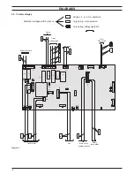
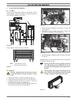
3.2 Circuit voltages
figure 3.2
Electrical voltages with burner on
during c.h. or d.h.w. operation
only during
c.h.
operation
only during
d.h.w.
operation
230
~
Safety
thermostat
0
Fan
0
Main circuit
3
D
L
2
D
L
1
D
L
2
F
1
F
F3
K1
K2
K3
K4
LD4
P6
T3
X1
X2
X3
X5
X6
X7
X10
X11
X12
X1
3
X17
X23
X24
P3
X14
X15
SB1
X16
X2
2
X9
Supply network
230
~
Pump
230
~
0
230
~
0
3 way
diverter valve
230~
Gas valve
24
~
Transformer
24
=
230
~
0
5=
D.h.w.
Flow switch
pressure switch