


- 25 -
GAS vALvE
11 GAS vALvE
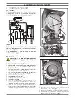
11.1 function
The gas valve A in Figure 11.1 controls the gas inflow to the boiler
burner.
figure 11.1
A
By means of an electric command given to the on-off operators
the passage of the gas through the Gas valve can be opened or
closed.
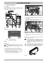
11.2 Nomenclature of the parts
- (figure 11.2)
B
Maximum gas pressure adjustment
C
Minimum gas pressure adjustment
D
On-off operators
E
On-off operators electric connector
f
Gas valve inlet pressure test point
figure 11.2
f
E
D
B
C
11.3 Adjustment
Warning: isolate the boiler from the mains electrici-
ty supply before removing any covering or compo-
nent.
Check the supply pressure before making any adjustment
to the gas valve.
1 Close the gas inlet valve.
2 Remove the front panel of the case and lower the control panel
(see sections "Body panels" and "Control panel" page 5).
3 Loosen the internal screw on the Inlet Pressure Test Point F
(Figure 11.2) of the Gas valve and connect a pressure gauge
using a suitable hose.
4 Open the gas inlet valve.
5 Turn on the electricity supply to the boiler, switching on the
fused spur isolation switch. The appliance operation light on
the left will flash every 4 seconds.
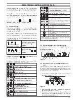
6 Set the function knobs as illustrated in Figure 11.4.
7 Open at least one hot water tap fully.
8 Read the inlet pressure value and ensure that it is within the
limits given in the table
Gas supply pressures
, of the user/in-
stallation manual If it does not comply with the required pres-
sure check the gas supply line and governor for faults and/or
correct adjustment.
9 Switch off the boiler close the gas inlet valve and close the
water tap.
10 Disconnect the pressure gauge and close the Inlet Pressure
Test Point F (Figure 11.2).
Gas valve adjustment
The person carrying out a combustion measurement
should have been assessed as competent in the use of
a flue gas analyser and the interpretation of the re-
sults. The flue gas analyser used should be one meet-
ing the requirements of BS7927 or BS-EN50379-3 and
be calibrated in accordance with the analyser manu-
facturers’ requirements, and have a current calibration
certificate.
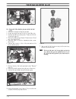
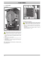
11 Fit the probe of the flue analyser in the flue exhaust sampling
point located on the exhaust pipes of the boiler (Figure 11.3).
figure 11.3
flue exhaust
sampling points
air sampling
points
12 Turn on the boiler, switching on the fused spur isolation
switch.
13 Open the gas inlet valve.
14 Set the function knob 8 as indicated in Figure 11.4. The ap-
pliance operation light on the left will flash every 4 seconds.