


- 13 -
D.H.W. HEAT ExCHANGER
6
D.H.W. HEAT ExCHANGER
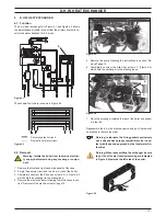
6.1 function
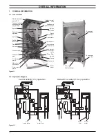
The d.h.w heat exchanger A in Figure 6.1 and Figure 6.3 allows
the instantaneous transfer of heat from the primary hydraulic cir-
cuit to the water destined for d.h.w use.
figure 6.1
A
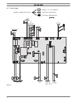
The schematic structure is shown in Figure 6.2.
figure 6.2
Primary hydraulic circuit
Domestic hot water circuit
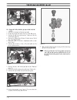
6.2 Removal
Warning: isolate the boiler from the mains electrici-
ty supply before removing any covering or compo-
nent.
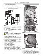
1 Remove the front and right hand side panels of the case.
2 Empty the primary circuit and the d.h.w circuit of the boiler.
3 Completely unscrew the Allen key screws B in Figure 6.3
which hold the exchanger to the brass group.
4 Remove the electric actuator following the instructions in sec-
tion "Removal of the electric actuator" page 15.
figure 6.3
B
A
5 Remove the pump following the instructions in section "Re-
moval" page 14.
6 Completely unscrew the Allen key screws C (Figure 6.4)
which hold the exchanger to the plastic groups.
figure 6.4
A
C
7 Move the exchanger towards the rear of the boiler and extract
it to the left.
Reassemble the d.h.w. heat exchanger carrying out the removal
operations in the reverse order.
Warning: to lubricate the o-ring gaskets exclusively
use a silicone base grease compatible to be in con-
tact with foods and approved by the local water Au-
thorities.
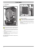
Warning: When reassembling the exchanger be sure
to put the off center location/securing pin indicated
in figure 6.5 towards the left side of the boiler.
figure 6.5