


- 31 -
D.H.W. fLoW SWITCH, fILTER AND fLoW LIMITER
14 D.H.W. fLoW SWITCH, fILTER AND fLoW LIMITER
14.1 function
The d.h.w. flow switch A in Figure 14.1 is a device that generates
an electrical signal when hot water is drawn.
figure 14.1
A
When the flow rate through the d.h.w. circuit reaches about 2,5
litres/min’, the float 5 (Figure 14.3) is dragged upwards and the
magnet in it, getting closer to the sensor 8, closes the electric
contact that switches the boiler d.h.w operation ON.
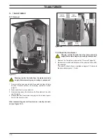
figure 14.2
B
C
D
14.2 Nomenclature and location of parts
- (figure 14.3)
1
Flow switch plug
2
O-ring
3
Flow limiter (optional for M96A.32SM/...)
4
Body
5
Float
6
Filter
7
Sensor holder spring
8
Sensor
figure 14.3
2
1
3
4
5
6
7
8
14.3 Checks
Warning: isolate the boiler from the mains electrici-
ty supply before removing any covering or compo-
nent.
Sensor operation
1 Remove the front panel of the case.
2 Measure the electrical resistance at the leads of the sensor.
Without water being drawn, the contact must be open. By
opening a hot water tap the contact must be close (electrical
resistance zero Ω).
14.4 Removal of the sensor
Warning: isolate the boiler from the mains electrici-
ty supply before removing any covering or compo-
nent.
1 Remove the front panel of the case.
2 Disconnect the connectors B and remove the sensor holder
spring 7 (Figure 14.2 - Figure 14.3).
3 Remove the sensor.
14.5 Removal of the flow switch group and d.h.w.
circuit filter
Warning: isolate the boiler from the mains electrici-
ty supply before removing any covering or compo-
nent.
1 Remove the front panel of the case and empty the d.h.w. circuit.
2 Remove the sensor (see section "Removal of the sensor"
page 31).
3 Remove the fork D and pull up the flow switch plug 1 (Figure
14.2 - Figure 14.3) with the help of a screwdriver.
4 To remove the filter from the flow switch group separate the
filter 6 from the body 4 (Figure 14.3) by levering it.
5 Reassemble the parts following the removing sequence in
reverse order.