


- 17 -
ELECTRoNIC CoNTRoL/IGNITIoN P.C.B.
9
ELECTRoNIC CoNTRoL/IGNITIoN P.C.B.
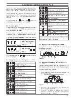
9.1 function
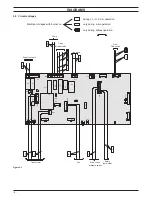
figure 9.1
From other boiler devices....
C.h. temperature probe NTC
D.h.w. temperature probe NTC
D.h.w. flow switch
Primary circuit flow switch
Flue temperature probe NTC
Safety thermal fuse
Safety thermostat
Flame detection electrode
Room thermostat (if fitted)
Time switch
On
the
Electronic
control/ignition
p.c.b.......
Function control
C.h. temperature adjustment
D.h.w. temperature adjustment
Boiler reset button
(control panel fascia)
Inlet Information
Pump
Three way diverter valve
Gas valve
Fan
Ignition electrodes
Appliance operation lights*
Lock---out signal lamp*
*control panel fascia
Outlet command
The fundamental function of the Electronic control/ignition p.c.b.
is that of controlling the boiler in relation to the external needs
(i.e. heating the dwelling or heating the water for d.h.w. use) and
operating in order to keep the temperature of the hydraulic cir-
cuits constant.
This is obviously possible within the useful power and maximum
working temperature limits foreseen.
Generally, the Electronic control/ignition p.c.b. receives inlet
information coming from the boiler (the sensors) or from the
outside (knobs, room thermostat, etc.), processes it and conse-
quently acts with outlet commands on other components of the
boiler (Figure 9.1).
The Electronic control/ignition p.c.b. is also a full sequence igni-
tion device and does a sequence of operations (ignition cycle)
which lead to the ignition of the gas at the burner.
It checks the presence of the flame during the entire period in
which it is activated and supplies the fan regulating its speed.
The Electronic control/ignition p.c.b. has a safety function and
any incorrect interventions or tampering can result in conditions
of dangerous functioning of the boiler.
The Electronic control/ignition p.c.b. can lock the functioning of
the boiler (lock state) and stop its functioning up to the resetting
intervention. The lock is signalled by the lighting of the lock---out
signal lamp and the device can be reset only by using the boiler
reset button placed on the control panel fascia.
Some components which are connected to the device can acti-
vate the lock state. The causes of a lock state could be:
• The intervention of the safety thermostat (overheat of the pri-
mary circuit).
• The intervention of the flue temperature probe (overheat of the
combustion products).
• A fault on gas supply.
• Faulty ignition (faulty ignition electrodes, their wiring or connection).
• Faulty flame detection (faulty detection electrode, its wiring or
connection).
• Faulty condensate drainage.
• Faulty gas valve (faulty on-off operators or not electrically supplied).
• Faulty Electronic control/ignition p.c.b.
Other components like the primary circuit flow switch can tempo-
rarily stop the ignition of the burner but allow its ignition when the
cause of the intervention has stopped.
Figure 9.15 and Figure 9.16 show the sequence of the opera-
tions that are carried out at the start of every ignition cycle and
during normal functioning.
9.2 Selection and adjustment devices
On the Electronic control/ignition p.c.b. several selection, adjust-
ment and protection devices are located. (Figure 9.2).
Some of these devices are directly accessible by the user (func-
tion control, temperature adjustment potentiometers etc.) others,
like the fuses, are accessible by removing the service panel.