Biasi M110B.24SM/E Скачать руководство пользователя страница 21

- 21 -

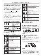
ELECTRoNIC CoNTRoL/IGNITIoN P.C.B.

The spare electronic control/ignition p.c.b. is set for natural gas.

If the boiler is fed with different gas type, go through the Gas 

conversion operations described in the Installation manual.

If an external temperature probe (optional) is fitted, the coef-

ficient K has also to be set as described in the Commission-

ing chapter of the installation manual.

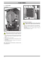
1  Gain access to the parts located inside the control panel as 

explained in the section "Control panel" page 5.

2  Remove all the wiring connected to the Electronic control/

ignition p.c.b.

  To disconnect the connectors delicately flex the hook present 

on one side of each socket.

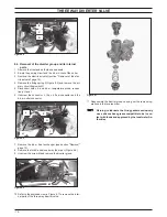
3  Remove the spindles of the c.h. and d.h.w. temperature ad-

justment knobs by delicately pulling them with pliers in the 
direction shown by the arrow in Figure 9.13.

figure 9.13

4  Unscrew the four screws that hold the Electronic control/igni-

tion p.c.b. on to the control panel.

5  Remove it by lifting its rear edge and freeing it from any of 

the wiring.

6  Re-assemble the Electronic control/ignition p.c.b. following 

the removal procedures in the reverse order.

Important

When re-assembling the Electronic control/ignition p.c.b.:
7  It is not necessary to utilise static protections but it is advis-

able to ensure that the p.c.b. is handled with care and held at 
the edges and with clean dry hands.

8  Fit the p.c.b. into the control panel by first inserting the front 

lower edge under the control knob shafts. Lower the rear 
edge and ensure that no wiring is trapped beneath.

9  Insert the spindles in the control panel knobs until the notch A 

(Figure 9.14) reaches the potentiometer edge. It is not neces-
sary to force them in the knob.

10  While tightening the screws that fix the Electronic control/igni-

tion p.c.b. on the control panel, keep the p.c.b. towards the 
control panel fascia making sure of the contact between the 
boiler reset button B and the tab C (Figure 9.14).

figure 9.14


A


Attention

After installing the Electronic control/ignition p.c.b.:
11  Make sure the c.h. (

) and d.h.w. (

) temperature ad-

justment knobs can move freely for the complete range.

  If not, remove the spindle again as described at step 3, turn 

the knob half a turn and re-insert the spindle.

12  Make sure that the settings comply with the indications given 

in section "Setting the boiler control function modes" page 19.

13  Operate the boiler and close the gas inlet cock so that the 

boiler goes into the safety lock-out state.

  Verify the correct operation of the boiler reset button by 

pressing and releasing it.

Warning: After cleaning or replacement as detailed 

above, if it deemed necessary to undertake a com-

bustion analysis as detailed in section "Removal" 

page 28.

Содержание M110B.24SM/E

Страница 1: ...Leave this manual adjacent to the gas meter Warning Service repairs must be carried out only by a qualified Gas Safety Registered Engineer who will be responsible for the current Regulations for gas...

Страница 2: ......

Страница 3: ...ture of the parts 25 11 3 Adjustment 25 11 4 Checks 26 11 5 Removal of the gas valve 26 12 Primary circuit flow switch 28 12 1 Function 28 12 2 Checks 28 12 3 Removal 28 13 Expansion vessel and temper...

Страница 4: ...h w Flow Switch Spark Generator C h pressure relief valve Safety thermal fuse Fan Safety thermostat Burner D h w temp probe Detection electrode Diverter valve Main circuit flow switch Flue temperatur...

Страница 5: ...l and remove it Figure 2 2 A To remove the side panels loosen the screws C and D Figure 2 3 bring the base of the panels away from the boiler and lift them freeing them from the top hooks Figure 2 3 B...

Страница 6: ...ry circuit 1 Close the c h circuit flow and return cocks H Figure 2 7 Figure 2 7 H I H Bottom view of the boiler 2 Remove the front and right panels of the boiler 3 Open the drain tap J Figure 2 8 unt...

Страница 7: ...P6 T3 X1 X2 X3 X5 X6 X7 X10 X11 X12 X13 X17 X23 X24 P3 X14 X15 SB1 X16 X22 X9 bu bn bu bn n b n b u b u b L N gnye bu bn bn bk bu bn bu gnye bn bk bu bn gnye bu gnye u b n b rd wh bk bu bn gnye gnye...

Страница 8: ...tion only during d h w operation 230 Safety thermostat 0 Fan 0 Main circuit 3 D L 2 D L 1 D L 2 F 1 F F3 K1 K2 K3 K4 LD4 P6 T3 X1 X2 X3 X5 X6 X7 X10 X11 X12 X13 X17 X23 X24 P3 X14 X15 SB1 X16 X22 X9 S...

Страница 9: ...Expansion vessel Safety valve Pressure gauge By pressing the reset push button the boiler turns on and operates cor rectly By pressing the reset push button the boiler starts the ignition cycle The b...

Страница 10: ...eration in c h mode 8 OFF Low d h w flow rate Water leaks from the safety valve dur ing operation on c h Water leaks from the safety valve when the boiler is off Note Useful information can be obtaine...

Страница 11: ...onnect the detection electrode connector D the ignition electrodes connector E and the earth wire F 4 Disconnect the fan connector G by pressing the plastic hook placed on the side of the connector Fi...

Страница 12: ...er clean with a bristle paintbrush and remove the dust with a hoover Warning After cleaning or replacement as detailed above if it deemed necessary to undertake a com bustion analysis as detailed in c...

Страница 13: ...ch hold the exchanger to the brass group 4 Remove the electric actuator following the instructions in sec tion Removal of the electric actuator page 15 Figure 6 3 B A 5 Remove the pump following the i...

Страница 14: ...plug from the pump Start the boiler and with a screwdriver turn the rotor in the direction of the arrow If there is a defect in starting the rotor will begin to turn normally only starting it manuall...

Страница 15: ...he actuator B brass spindle when the boiler operates in c h mode In both figures the relationship between the position of the actua tor and the resistance of the motor windings the motor must be disco...

Страница 16: ...screw the connector J the c h flow connector and the d h w outlet connector Figure 8 5 F G H I J 7 Remove the d h w heat exchanger see section Removal page 13 8 Remove the fork K and move away the pip...

Страница 17: ...ted and supplies the fan regulating its speed The Electronic control ignition p c b has a safety function and any incorrect interventions or tampering can result in conditions of dangerous functioning...

Страница 18: ...ter flow temperature and d h w outlet temperature The temperature of the water is converted into an electric signal by means of temperature probes The user setting the desired temperature with the con...

Страница 19: ...tect operation D h w operation Excessive temperature on primary circuit Faulty c h temperature probe NTC Faulty d h w temperature probe NTC Faulty primary circuit no water or absence of flow Lack of b...

Страница 20: ...obtain it Figure 9 11 Where Lamp OFF Lamp ON At this step it is possible to visualize the current setting by keep ing the reset button 9 pressed for more than 5 seconds The lamps will flash a number o...

Страница 21: ...it is advis able to ensure that the p c b is handled with care and held at the edges and with clean dry hands 8 Fit the p c b into the control panel by first inserting the front lower edge under the c...

Страница 22: ...ture higher than 110 C YES NO beginning of wait period End of wait period YES NO YES starts ignition discharges Opens gas valve beginning of ignition period flame presence YES interrupts ignition disc...

Страница 23: ...cancels lock Is fan rpm exact NO YES Is flue temperature higher than 110 C YES NO beginning of wait period End of wait period YES NO starts ignition discharges Opens gas valve beginning of ignition pe...

Страница 24: ...rmer carrying out the removal opera tions in the reverse order After reassembling ensure the wires are correctly connect ed see Figure 10 2 Figure 10 2 larger connector larger connector smaller connec...

Страница 25: ...ry 4 seconds 6 Set the function knobs as illustrated in Figure 11 4 7 Open at least one hot water tap fully 8 Read the inlet pressure value and ensure that it is within the limits given in the table G...

Страница 26: ...rotate screw B Figure 11 2 by rotating it clockwise the CO2 decreases 25 Switch off the boiler and turn off the hot water tap s 26 Close the air flue sampling points 27 After adjustment fit the protec...

Страница 27: ...and turn the plastic screw inside it fully clockwise until it stops Do not over tight 9 Turn it counter clockwise 2 and 3 4 turns 10 Adjust the gas valve using the flue analyser as described in secti...

Страница 28: ...the position of the lever C referring to Figure 12 2 Figure 12 2 Boiler OFF Boiler ON C Electrical check It is possible to verify the general operation of the switch by measuring the electric resistan...

Страница 29: ...oncave side faces towards the actuator plate I and the reference in dicated aligns with the seat J see Figure 12 5 Warning to lubricate the O ring gaskets exclusively use a silicone base grease compat...

Страница 30: ...above the boiler and the rear exit flue can be easily removed the expansion vessel can be changed without removing the boiler Warning isolate the boiler from the mains electrici ty supply before remo...

Страница 31: ...Measure the electrical resistance at the leads of the sensor Without water being drawn the contact must be open By opening a hot water tap the contact must be close electrical resistance zero 14 4 Rem...

Страница 32: ...sizes are available Nominal flow rate litres min Colour 10 Blue 12 Red 14 Pink To install the flow limiter 1 Remove the flow switch group as explained in the section Removal of the flow switch group a...

Страница 33: ...the Temperature probe Measure the temperature of the pipe near the Temperature probe and check the electrical resistance according to the graph in Fig ure 15 1 15 3 Removal of the c h Temperature pro...

Страница 34: ...side of the diverter group Figure 16 1 A 16 2 Removal Warning isolate the boiler from the mains electrici ty supply before removing any covering or compo nent 1 Remove all the case panels 2 Empty the...

Страница 35: ...Figure 17 2 C D E F 3 Disconnect the air manifold C Figure 17 2 by pulling it Figure 17 3 Fan gasket G H I J K L 4 Disconnect the rubber pipe G Figure 17 3 Figure 17 4 M 5 Unscrew the gas connector M...

Страница 36: ...es connector E and the earth wire F from the spark generator C Figure 18 1 and disconnect the detection electrode connector G 3 Unscrew the screws H and remove the ignition electrodes B and the detect...

Страница 37: ...6 3 Remove the front insulation panel Figure 18 6 4 Assemble the new front insulation carrying out the removal op eration in reverse order When fitting the new panel ensure that the electrodes holes c...

Страница 38: ...ectrodes page 36 2 Check for the correct distance between the metallic edges of the ignition electrode see Figure 18 9 Figure 18 10 Figure 18 9 Ignition electrode 3 5 mm earth electrode Check the conn...

Страница 39: ...low that of the safety thermostat and no overheat intervention should occur Warning isolate the boiler from the mains electrici ty supply before removing any covering or compo nent Electrical function...

Страница 40: ...this safety device the heat exchanger part shown in Figure 20 3 may be damaged and must be replaced Figure 20 3 20 2 Removal Warning isolate the boiler from the mains electrici ty supply before removi...

Страница 41: ...flame detection electrode this will cause the boiler lock out 21 2 Check the cleanness of the trap Unscrew the plug on the bottom of the trap and remove dirt even tually deposit 21 3 Removal Warning...

Страница 42: ...telli Partners H58 718 Electronic regulation p c b mod M110B 32SM 1 BI1955 101 8 H22 543 D h w heat exchanger M110B 24SM 1 BI1181 122 E01 205 D h w heat exchanger M110B 32SM 1 BI1001 102 9 H58 670 Pum...

Страница 43: ...43 Short spare parts list P5 1 5 3 4 2 6 9 7 14 16 20 19 21 8 11 15 17 10 12 13 18 Figure 22 1...

Страница 44: ...Biasi UK Ltd Commercial Road Leamore Enterprise Park WALSALL WS2 7NQ Sales Tel 01922 714600 Tech Service Tel 01922 714636 www biasi co uk 1796214550 17962 1455 0 0412 44A4 UK 16 01 2012 N...

Отзывы: