Commissioning/Configuration
EP3356-0022
34
Version: 1.4
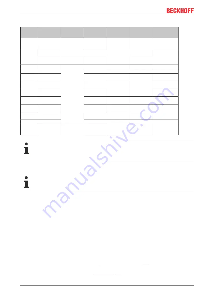
Overview of conversion times
Filter Set-
tings
Value
PDO update
time
Filter property
Limit frequency
(-3 dB) [Hz]
(typ.)
Comment
Rise time 10-90 %
[s] (typ.)
Filter deacti-
vated
-
Cycle-synchro-
nous,, min.
100 µs
-
-
-
-
0
FIR 50 Hz
312.5 µs
50 Hz notch filter 22 Hz
Typ. conversion
time 312.5 µs
0.013
1
FIR 60 Hz
260.4 µs
60 Hz notch filter 25 Hz
Typ. conversion
time 260.4 µs
0.016
2
IIR1
Cycle-synchro-
nous (up to min.
100 µs)
Low-pass
2000 Hz
a
0
=1/2
1
= 0.5
0.0003
3
IIR2
Low-pass
500 Hz
a
0
=1/2
2
= 0.25
0.0008
4
IIR3
Low-pass
125 Hz
a
0
=1/2
4
= 62.5e-
3
0.0035
5
IIR4
Low-pass
30 Hz
a
0
=1/2
6
= 15.6e-
3
0.014
6
IIR5
Low-pass
8 Hz
a
0
=1/2
8
= 3.91e-
3
0.056
7
IIR6
Low-pass
2 Hz
a
0
=1/2
10
= 977e-
6
0.225
8
IIR7
Low-pass
0.5 Hz
a
0
=1/2
12
= 244e-
6
0.9
9
IIR8
Low-pass
0.1 Hz
a
0
=1/2
14
= 61.0e-
6
3.6
10
Dynamic IIR
The filter changes dynamically between the filters IIR1 to IIR8
11
PDO Filter fre-
quency
1/PDO
Value[Hz]*64
Notch filter with
adjustable fre-
quency
ca. 0,443 * PDO
Value [Hz]
-
-
Filter and cycle time
If the FIR filters (50 Hz or 60 Hz) are switched on, the process data are updated maximally with the
specified conversion time (see table). The IIR filter works cycle-synchronously. Hence, a new mea-
sured value is available in each PLC cycle.
At which point the filters can be adjusted is described in the chapter “Object description and
parameterization” for example under index 0x8000:12.
IIR filter
Differential equation: Y
n
= X
n
* a
0
+ Y
n-1
* b
1
with a
0
+ b
1
= 1
a
0
= (see table), b
1
= 1 - a
0
Dynamic IIR Filter
The dynamic IIR filter automatically switches through the 8 different IIR filters depending on the weight
change. The idea:
• The target state is always the IIR8-Filter, i.e. the greatest possible damping and hence a very calm
measured value.
• In the input variable changes rapidly the filter is opened, i.e. switched to the next lower filter (if still
possible). This gives the signal edge more weight and the measured value curve can follow the load
quickly.
• If the measured value changes very little the filter is closed, i.e. switched to the next higher filter (if still
possible). Hence the static state is mapped with a high accuracy.
• The evaluation as to whether a downward change of filter is required or whether an upward change is
possible takes place continuously at fixed time intervals.
Parameterization takes place via the CoE entries
according to 2 parameters:
• The "Dynamic filter change time" object
is used to set the time interval at which the
existing signal is re-evaluated.
Содержание EP3356-0022
Страница 2: ......
Страница 79: ...Commissioning Configuration EP3356 0022 79 Version 1 4 Fig 49 Confirming program start ...
Страница 90: ......


