


Application of
Assembly
3 - 175
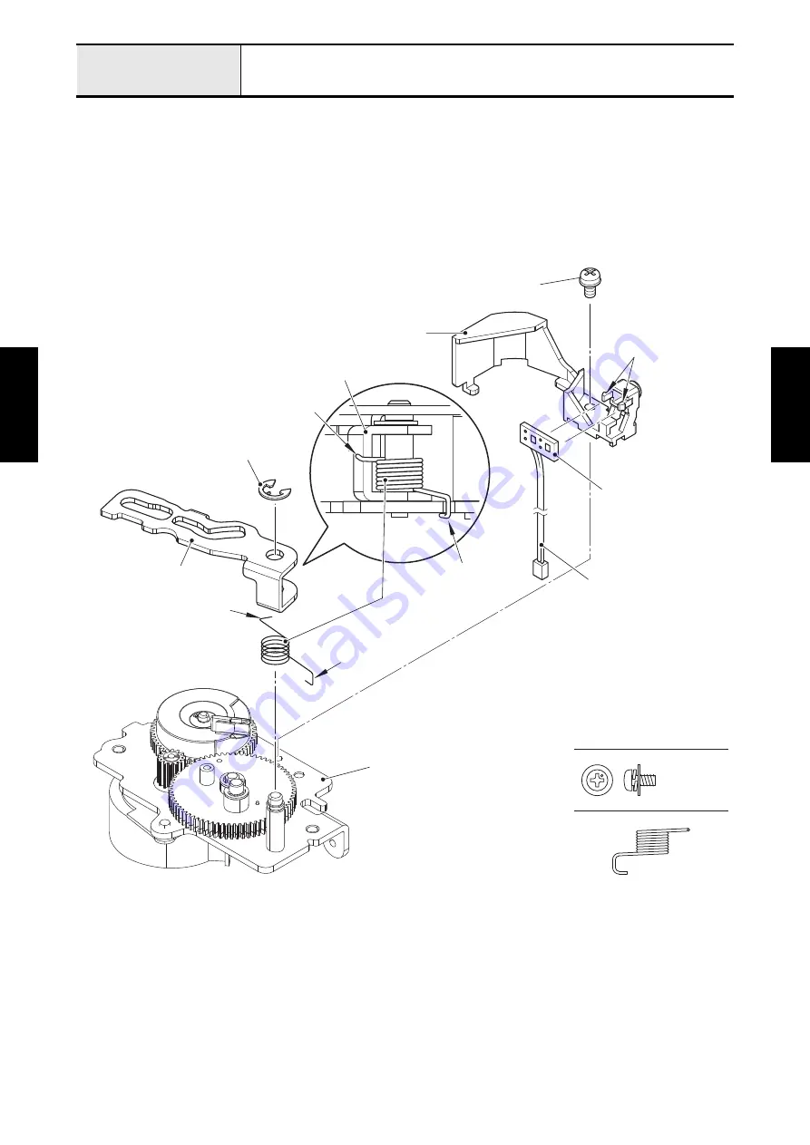
Thread cutter module
Application o
f
Assembly
Application of
Assembly
6. Set the photo transistor PCB assy to the sensor holder, and then hang the two hooks on the photo
transistor PCB assy. Pass the photo transistor PCB assy lead wire through the securing fixtures. Attach
the sensor holder to the motor holder assy with the screw (screw, pan (S/P washer) M3x6).
*Key point
• Refer to
"Wiring of Thread cutter module"
7. Assemble the thread cutter lever and spring, twist (XE4139), hang the end “A” of spring, twist (XE4139)
on the thread cutter lever, attach them to the shaft of motor holder assy, and then secure them with the
retaining ring E4. Hang the end “B” of spring, twist (XE4139) on the notch of motor holder assy.
SPRING, TWIST (XE4139)
Screw, Pan (S/P washer) M3X6
Screw, pan (S/P washer) M3x6
Thread cutter lever
Retaining ring E4
Thread cutter lever
“A”
“A”
“B”
“B”
Spring, twist
(XE4139)
Photo transistor
PCB assy
Motor holder assy
Hooks
Sensor holder
Photo transistor
PCB assy lead wire
Содержание BLDY
Страница 1: ...MODEL BLDY BLDY2 Home Sewing Machine SERVICE MANUAL Sep 2014 Jun 2016 Published Revised CONFIDENTIAL...
Страница 2: ......
Страница 3: ...LIST of UPDATE RECORD Date Added Models Contents Changed 4 13 Added 4 52 to 55 May 2015 Jun 2016 BLDY2...
Страница 275: ...Application of Assembly 3 177 Feed module Application of Assembly Application of Assembly Feed module location diagram...