


Application of
Assembly
3 - 118
Needle threading mechanism
Application o
f
Assembly
Application of
Assembly
6
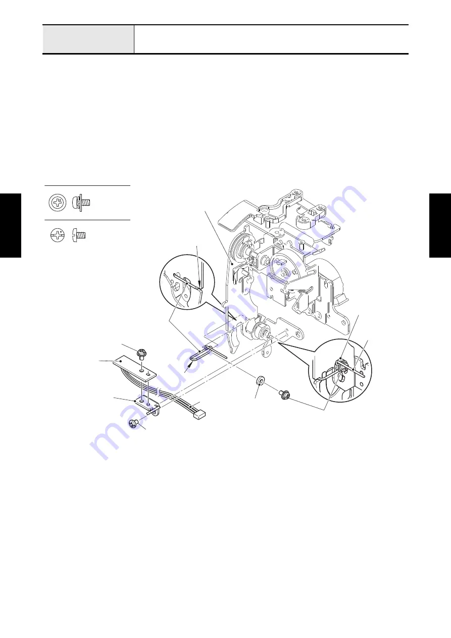
Attachment of Thread guide wire and Upthread PCB assy
1. Hang the bent part of thread guide wire on the notch of thread tension assy, and insert the tip of thread
guide wire into the positioning hole of thread tension assy. Set the washer plain between the thread
guide wire and thread tension assy. Attach the thread guide wire and the washer plain to the thread
tension assy with the screw (screw, pan (S/P washer) M3x6).
2. Align the positioning hole of thread sensor holder with the boss of thread tension assy, and attach the
thread sensor holder to the thread tension assy with the screw (screw, bind M3x4). Align the positioning
hole of upthread PCB assy with the boss of thread sensor holder, and attach the upthread PCB assy to
the thread sensor holder with the screw (screw, pan (S/P washer) M3x6). Pass the upthread PCB assy
lead wire through the securing fixtures.
*Key point
• Refer to
"Wiring of Needle thread module"
.
Screw, Bind M3X4
Screw, Pan (S/P washer) M3X6
Screw, pan (S/P washer) M3x6
Washer plain
Screw, bind M3x4
Thread sensor holder
Upthread PCB
assy
Thread guide wire
Notch
Thread tension assy
Thread guide wire
Screw, pan (S/P washer) M3x6
Washer plain
Bent part
Upthread PCB
assy lead wire
Содержание BLDY
Страница 1: ...MODEL BLDY BLDY2 Home Sewing Machine SERVICE MANUAL Sep 2014 Jun 2016 Published Revised CONFIDENTIAL...
Страница 2: ......
Страница 3: ...LIST of UPDATE RECORD Date Added Models Contents Changed 4 13 Added 4 52 to 55 May 2015 Jun 2016 BLDY2...
Страница 275: ...Application of Assembly 3 177 Feed module Application of Assembly Application of Assembly Feed module location diagram...