


Application of
Assembly
3 - 110
Lower driving mechanism
Application o
f
Assembly
Application of
Assembly
3
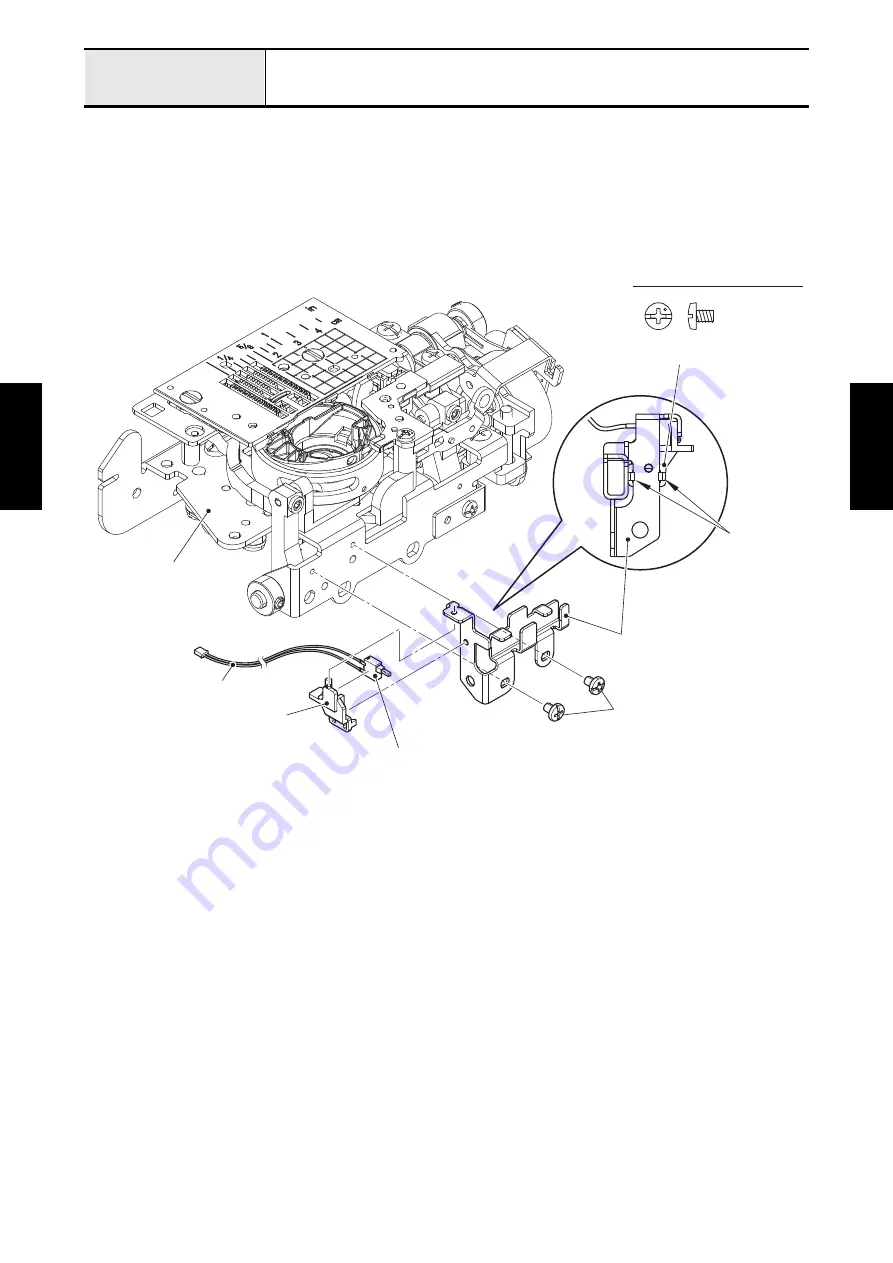
Attachment of Needle plate B switch assy and Lead wire guide holder
1. Set the needle plate B switch assy to the sensor holder. Align the two bosses of sensor holder with the
two positioning holes of lead wire guide holder, and attach the sensor holder to the lead wire guide
holder with the two hooks. Pass the needle plate B switch assy lead wire through the securing fixtures.
*Key point
• Refer to
"Wiring of Needle plate B switch assy"
2. Attach the lead wire guide holder to the feed module with the two screws (screw, bind M3x4).
Screw, Bind M3X4
Sensor holder
Hooks
Lead wire guide holder
Screw, bind M3x4
Sensor holder
Needle plate B switch assy
Feed module
Needle plate B switch assy lead wire
Содержание BLDY
Страница 1: ...MODEL BLDY BLDY2 Home Sewing Machine SERVICE MANUAL Sep 2014 Jun 2016 Published Revised CONFIDENTIAL...
Страница 2: ......
Страница 3: ...LIST of UPDATE RECORD Date Added Models Contents Changed 4 13 Added 4 52 to 55 May 2015 Jun 2016 BLDY2...
Страница 275: ...Application of Assembly 3 177 Feed module Application of Assembly Application of Assembly Feed module location diagram...