background image

Application of 

Disassembly

3 - 56

Thread cutter module

Application o

Disassembly 

Application of  Disassembly 

Thread cutter module location diagram

Содержание BLDY

Страница 1: ...MODEL BLDY BLDY2 Home Sewing Machine SERVICE MANUAL Sep 2014 Jun 2016 Published Revised CONFIDENTIAL...

Страница 2: ......

Страница 3: ...LIST of UPDATE RECORD Date Added Models Contents Changed 4 13 Added 4 52 to 55 May 2015 Jun 2016 BLDY2...

Страница 4: ...of Rear cover assy 2 10 Removal of Free arm plate and Base plate cover 2 11 Removal of Knee lifter assembly Connector holder assy and UW pen connector PCB assy 2 12 Removal of LED PCB holder A B 2 13...

Страница 5: ...ain frame and covers 2 61 Attachment of Upper unit relay PCB assy 2 62 Attachment of LED PCB holder A B 2 63 Attachment of UW pen connector PCB assy Connector holder assy and Knee lifter assembly 2 64...

Страница 6: ...tting shutter 3 35 Removal of ATPM insulation assy and Tension release unit 3 36 Removal of Thread guide shutter link A B C 3 37 Lower driving mechanism 3 38 Removal of Reversal link assy Pull link an...

Страница 7: ...X carriage cover 3 82 Removal of E hoop stay plate assy 3 83 Disassembly of E hoop stay plate assy 3 84 Removal of ES main cover assy 3 85 Removal of EMB relay PCB assy 3 86 Removal of ES base cover...

Страница 8: ...chment of FC jack assy 3 139 Attachment of Panel board holder and Panel PCB assy 3 140 Attachment of Ground plate USB holder Head phone jack assy and USB cover 3 142 Attachment of Speaker assy and Lea...

Страница 9: ...Attachment of Inner rotary hook bracket assy Inner rotary hook assy and Needle plate A assy 3 189 Embroidery unit 3 190 Lubrication 3 191 Assembly of Timing belt 3 192 Attachment of X INIT PCB assy an...

Страница 10: ...of feed dog 4 31 Feed forward backward 4 32 Side feed straight stitch 4 34 One point 4 35 BH lever switch position 4 36 Inner rotary hook bracket position 4 38 Lower thread tension standard inner rot...

Страница 11: ...e 5 19 LED lamp does not light 5 20 Lower thread detection does not work normally 5 22 Upper thread sensor does not work normally 5 23 Automatic needle threader does not work correctly 5 24 Presser fo...

Страница 12: ...counter of the maintenance 6 2 Necessary grease oil 6 3 Maintenance point 6 4 7 Special Instructions of Wiring 7 1 Module wiring 7 2 Main body wiring 7 6 Front cover wiring 7 20 Embroidery unit wirin...

Страница 13: ...and after August 2 1976 Compliance is mandatory for products marketed in the United States One of the following labels on the back of the sewing machine indicates compliance with the FDA regulations...

Страница 14: ...a laser diode which emits visible laser radiation in the Laser module Do not disassemble the Laser module Since the variable resistor in the laser module is adjusted in accordance with the standards n...

Страница 15: ...nce instructions for VBG 93 are valid CAUTION In case of any trouble with the Laser module replace the Laser module itself To prevent direct exposure to the laser beam do not try to disassemble the La...

Страница 16: ...1 Main mechanisms 1 2 Driveline 1 3 Positions of electronic components 1 5 Control system block diagram 1 7 Layout for PCB connectors 1 8 Operation of other electronic components 1 10 Outline of Mecha...

Страница 17: ...aft mechanism Side feed mechanism Lower shaft mechanism Feed dog drop mechanism Feed Rotary hook mechanism Thread cutting mechanism Bobbin winder mechanism Thread tension mechanism Needle thread drive...

Страница 18: ...supporter assy Needle bar crank rod Needle bar block Needle bar hook stand Unit shaft Needle Needle bar Needle bar release lever Joint Upper shaft Pulley Z zigzag cam Z pulse motor Z zigzag lever Thre...

Страница 19: ...or Side feed bar Side feed plate Feed arm A Vertical lever Outer rotary hook Feed bar Vertical adjusting screw Feed dog Feed arm B F pulse motor Lower shaft A Joint Vertical lever Outer rotary hook Lo...

Страница 20: ...wer thread LED diode PCB Lower thread phototransistor PCB Needle plate switch 1 LED PCB Needle area L Button hole switching switch Zigzag pulse motor sensor PCB Cloth thickness variable resistance Zig...

Страница 21: ...utline of Mechanism Outline of Mechanism Positions of electronic components Embroidery unit Y relay PCB Y initial sensor PCB Embroidery frame detective PCB Embroidery relay PCB X pulse motor Y pulse m...

Страница 22: ...ler MFFC MFFC jack DPM sensor PCB SPM sensor PCB UW pen connector PCB Ultrasonic wave pen SS LED x 2 SS key BK key SS PCB NP key CUT key ATP key LK key LK LED Panel PCB Main PCB Embroidery unit 24V 12...

Страница 23: ...tor PCB 5 1 CN24 KLPOT Knee lifter sensor 3 1 CN28 PLT1 Needle plate A detection switch 2 1 CN29 PLT2 Needle plate B detection switch 2 1 CN25 FINT Feed pulsemotor sensor PCB 3 1 CN27 CINT Cutter puls...

Страница 24: ...1 1 HOST 2 1 3 4 CN7 LCDM LCD module 1 40 CN14 AUD_2 Head phone jack 4 1 CN12 AUD Speaker 2 1 CN18 SRD Not used 4 1 CN11 CAMERA Camera relay PCB 1 21 CN10 TP Touch panel 1 4 CN6 SS Start Stop switch P...

Страница 25: ...This button toggles the presser foot between the up and down positions Speed control lever This lever controls the speed of sewing Needle thread button Press this button the machine automatically thr...

Страница 26: ...cts the bobbin thread is low Laser drive PCB assy This PCB assy irradiates line focused laser for the laser guide line marker and detects initial position of the laser module pulse motor UWR ultrasoni...

Страница 27: ...eparation 2 2 Main frame and covers 2 3 Electric parts and Main motor unit 2 15 Needle threading mechanism 2 21 Lower driving mechanism 2 24 LED lamp Upper driving mechanism 2 28 Assembly LED lamp Upp...

Страница 28: ...y 1 Disconnecting cables and removing accessories Needle Presser foot Needle plate cover Bobbin Power cord if connected USB I F core cable if connected UW sensor pen if connected Foot controller if co...

Страница 29: ...Basic of Disassembly Basic of Disassembly 2 3 Main frame and covers Basic of Disassembly Main frame and covers location diagram...

Страница 30: ...asic of Disassembly 1 Removal of Top cover unit assy and Accessory table assy 1 Remove the top cover unit assy from the machine 2 Remove the accessory table assy from the machine Refer to 3 3 Disassem...

Страница 31: ...plate B assy 2 Remove the screw screw bind M4x6 and then remove the free arm cover 3 Remove the screw screw pan T washer M3x6 and screw screw bind M3x6 release the hook from the hook tray and remove...

Страница 32: ...S P washer M4x8 from the face plate assy to remove it from the machine Refer to 3 4 Disassembly of Face plate assy 2 Remove the screw cap and the screw screw bind M4x6 from the front thread guard cove...

Страница 33: ...er from the each cover to remove the belt cover Refer to 3 5 Disassembly of Belt cover assy 3 Remove the two screws screw bind M4x6 Release the each hook of the belt cover lower assy from the each cov...

Страница 34: ...tor of lead wire assy BW from the main PCB assy 3 Remove the bobbin winder unit cover assy from the machine Disconnect the lead wire assy RGBLED from the RGB LED PCB assy of the bobbin winder unit cov...

Страница 35: ...er side of front cover assy and release the three hooks E from the base plate to remove the front cover assy 3 Disconnect the lead wire assy main panel from the main PCB assy Unlock the lock to discon...

Страница 36: ...nd screw screw bind M3x4 from the rear cover assy 2 Release the three hooks from the base plate to remove the rear cover assy Refer to 3 16 Disassembly of Rear cover assy Taptite Cup B M4X14 Screw Bin...

Страница 37: ...ate cover 1 Remove the two screws taptite bind S M4x10 to remove the free arm plate from the arm bed 2 Remove the two screws screw bind M4x6 to remove the base plate cover from the base plate Screw Bi...

Страница 38: ...of Connector holder assy 3 Disconnect the lead wire assy pen connector from the main PCB assy and UW pen connector PCB assy Remove the two screws screw bind M3x6 to remove the UW pen connector PCB as...

Страница 39: ...the screw taptite bind S M4x10 to remove the LED PCB holder A Remove the screw screw pan S P washer M3x7 to remove the LED PCB assy work area from the LED PCB holder A 3 Remove the screw taptite bind...

Страница 40: ...ad wire and the lead wire assy PFPM from the main PCB assy and release them from securing fixtures 3 Disconnect all the connector connected to the upper unit relay PCB assy 4 Remove the two screws tap...

Страница 41: ...Basic of Disassembly Basic of Disassembly 2 15 Electric parts and Main motor unit Basic of Disassembly Electric parts and Main motor unit location diagram...

Страница 42: ...ct all the connector connected to the main PCB assy 2 Remove the four screws screw pan S P washer M4x10DB to remove the two clips and the main PCB assy 3 Release the three hooks to remove the main PCB...

Страница 43: ...the connector of main motor assembly lead wire from the power PCB assy of power unit 3 Release the clip to unbind the main motor assembly lead wire 4 Remove the two screws upset M4x12DB to remove the...

Страница 44: ...ead wire assy power main and the lead wire assy motor drive from the hole of arm bed 2 Release the lead wire of inlet assy from the securing fixtures of power unit and then unlock the connector of inl...

Страница 45: ...tube 1 Release the each lead wire from the securing fixtures 2 Remove the screw screw pan S P washer M4x10DB to remove the cord clamp and then remove it from the spiral tube 3 Release the spiral tube...

Страница 46: ...nsion IF PCB assy 1 Release the extension IF PCB assy lead wire from the securing fixtures 2 Remove the two screws screw bind M3x4 to remove the extension IF PCB assy from the extension connector hold...

Страница 47: ...Basic of Disassembly Basic of Disassembly 2 21 Needle threading mechanism Basic of Disassembly Needle threading mechanism location diagram...

Страница 48: ...acer from the LED lamp holder L assy 3 Remove the screw screw bind M3x4 and two screws taptite bind S M4x10 to remove the LED lamp holder L assy from the arm bed Refer to 3 44 Disassembly of LED lamp...

Страница 49: ...read unit assy from the securing fixtures 2 Remove the screw screw bind M4x8 to remove the front cover fixed plate from the thread unit assy 3 Remove the two screws screw bind M4x8 to remove the threa...

Страница 50: ...Basic of Disassembly Basic of Disassembly 2 24 Lower driving mechanism Basic of Disassembly Lower driving mechanism location diagram...

Страница 51: ...lead wire 2 Remove the screw screw bind M3x6 to remove the spring plate B and the washer from the side feed adjust plate 3 Remove the two screws taptite bind S M4x10 to remove the side feed assy from...

Страница 52: ...o screws screw M4 to remove the feed module from the arm bed Refer to 3 46 Feed module 3 Cut the two bands and release the each lead wire from the securing fixtures 4 Remove the two screws screw bind...

Страница 53: ...ws taptite bind S M4x10 to remove the bushing presser from the arm bed 5 Remove the two screws taptite bind S M4x10 to remove the bushing presser A from the arm bed 6 Remove the lower shaft A assy fro...

Страница 54: ...Basic of Disassembly Basic of Disassembly 2 28 LED lamp Upper driving mechanism Basic of Disassembly LED lamp Upper driving mechanism location diagram...

Страница 55: ...per driving mechanism Basic of Disassembly 1 Removal of Tension pulley assy 1 Remove the screw upset M4x12DB to remove the tension pulley assy from the tension pulley holder B assy Upset M4X12DB Tensi...

Страница 56: ...ptite bind B M3x8 and then remove the cord guide from the upper shaft cover 2 Remove the three screws screw pan S P washer M4x10DB to remove the upper shaft cover from the arm bed Refer to 3 43 Disass...

Страница 57: ...belt support upper and the metal presser Remove the two screws screw pan S P washer M3x6 to remove the belt support upper adjust from the belt support upper 3 Remove the fixed joint and timing belt fr...

Страница 58: ...d the lead wire assy laser module from the securing fixtures 2 Remove the two screws screw pan S P washer M3x11 to remove the laser module assy while pulling the film down 3 Disconnect the lead wire a...

Страница 59: ...rew bind M3x6 to remove the LED holder spacer 2 Remove the two screws taptite bind S M4x10 to remove the plate K and the LED lamp holder R assy from the arm bed Refer to 3 44 Disassembly of LED lamp h...

Страница 60: ...drive unit assy 1 Release the two lead wires of thread drive unit assy and seven lead wires of needle presser module from the securing fixtures 2 Remove the two screws taptite bind B M4x10 to remove...

Страница 61: ...mp Upper driving mechanism Basic of Disassembly 3 Remove the two screws taptite bind B M4x10 and then remove the thread drive unit assy from the needle presser module Taptite Bind B M4X10 Thread drive...

Страница 62: ...remove the presser plate A and then remove the two screws taptite bind S M4x10 to remove the presser plate B Remove the needle presser module from the arm bed 4 Remove the shaft from the needle presse...

Страница 63: ...Basic of Assembly 2 37 LED lamp Upper driving mechanism Basic of Assembly Basic of Assembly LED lamp Upper driving mechanism location diagram...

Страница 64: ...Assembly 2 38 LED lamp Upper driving mechanism Basic of Assembly Basic of Assembly 1 Lubrication Lubrication point Lubricating oil type Quantity of lubrication 1 Felt 1 place FBK OIL RO 100 1 to 2 dro...

Страница 65: ...screws taptite bind S M4x10 and then attach the presser plate B to the arm bed with the two screws taptite bind S M4x10 3 Tighten the screw screw pan washer M3x18 temporarily to the needle presser mod...

Страница 66: ...sembly 3 Attachment of Thread drive unit assy 1 Set the rack to the lever AB and attach the thread drive unit assy to the needle presser module with the two screws taptite bind B M4x10 Taptite Bind B...

Страница 67: ...he BH switch assy lead wire through the securing fixtures Attach the cord guide to the needle presser module with the two screws taptite bind B M4x10 3 Pass the lead wire assy PFPM the PF INIT PCB ass...

Страница 68: ...ssy and the plate K to the arm bed with the two screws taptite bind S M4x10 Refer to 3 106 Assembly of LED lamp holder R assy 2 Attach the LED holder spacer to the needle presser module with the screw...

Страница 69: ...ule assy to the thread drive unit assy with the two screws screw pan S P washer M3x11 while pulling the film down 3 Pass the lead wire assy laser module and the LM pulse motor lead wire through the se...

Страница 70: ...nt side 6 Turn the fixed joint with two screw holes A to the front side slide the fixed joint to the direction of the arrow and insert it into the unit shaft Be sure to make 0 5 mm gap between the ret...

Страница 71: ...with the three screws screw pan S P washer M4x10DB Refer to 3 107 Assembly of Upper shaft cover 2 Set the cord guide to the upper shaft cover and the connecting PCB holder then secure it with the scr...

Страница 72: ...g hole of tension pulley assy with the boss of tension pulley holder B assy set the tension pulley assy to the tension pulley holder B assy and tighten the screw upset M4x12DB temporarily Key point Fu...

Страница 73: ...Basic of Assembly 2 47 Lower driving mechanism Basic of Assembly Basic of Assembly Lower driving mechanism location diagram...

Страница 74: ...tity of lubrication 1 Felt 2 places FBK OIL RO 100 1 to 2 drops 2 Disk 2 places EPNOC AP N 0 Rice grain size 3 Side feed assy 1 place MOLYKOTE EM30L Small amount 4 DPM insulation assy 1 place EPNOC AP...

Страница 75: ...A assy 6 Set the disk to the joint of lower shaft A assy 7 Set the belt support lower to the tension pulley holder B assy and tighten the two screws screw pan S P washer M3x6 temporarily Key point Fu...

Страница 76: ...th the disk align the two positioning holes of feed module with the two pins of arm bed and set the feed module to the arm bed with the two screws screw M4 Refer to 3 177 Feed module 4 Set the pull li...

Страница 77: ...adjust plate set the washer to the side feed adjust plate align the notch of spring plate B with the boss and attach the spring plate B to the side feed adjust plate with the screw screw bind M3x6 3 C...

Страница 78: ...Basic of Assembly 2 52 Needle threading mechanism Basic of Assembly Basic of Assembly Needle threading mechanism location diagram...

Страница 79: ...dle threading mechanism 2 Align the boss of front cover fixed plate with the positioning hole of thread unit assy and attach the front cover fixed plate to the thread unit assy with the screw screw bi...

Страница 80: ...er to 3 106 Assembly of LED lamp holder L assy 2 Attach the LED holder spacer to the LED lamp holder L assy with the screw screw pan P washer M3x12 3 Pass the lead wire assy LED2 through the securing...

Страница 81: ...Basic of Assembly 2 55 Electric parts and Main motor unit Basic of Assembly Basic of Assembly Electric parts and Main motor unit location diagram...

Страница 82: ...y with the boss of extension connector holder U and attach the extension IF PCB assy to the extension connector holder U with the two screws screw bind M3x4 2 Pass the extension IF PCB assy lead wire...

Страница 83: ...ith the spiral tube 2 Set the cord clamp to the spiral tube and then attach the cord clamp to the arm bed with the screw screw pan S P washer M4x10DB 3 Pass the each lead wire through the securing fix...

Страница 84: ...unit to the arm bed with the three screws screw pan S P washer M4x10DB align the boss of the inlet assy with the positioning hole of arm bed and attach the inlet assy with the screw screw pan S P was...

Страница 85: ...y of Main motor assembly 2 Connect the connector of main motor assembly lead wire to the power PCB assy of power unit and secure the ferrite core of main motor assembly lead wire with the clip Key poi...

Страница 86: ...and secure it with the three hooks 2 Attach the main PCB assy and the two clips to the arm bed with the four screws screw pan S P washer M4x10DB 3 Connect the each connector to the lower side of main...

Страница 87: ...Basic of Assembly 2 61 Main frame and covers Basic of Assembly Basic of Assembly Main frame and covers location diagram...

Страница 88: ...ad wire assy PFPM through the securing fixtures and connect them to the main PCB assy 4 Connect the lead wire assy upper relay1 and the lead wire assy upper relay2 to the upper relay PCB assy pass the...

Страница 89: ...assy work area with the screw screw pan S P washer M3x7 Attach the LED PCB holder B to the arm bed with the screw taptite bind S M4x10 3 Connect the two connectors of lead wire assy LED1 to the two LE...

Страница 90: ...he base plate with the two screws screw bind M4x6 Connect the lead wire assy main body to the main PCB assy bind up the each lead wire to the side feed assy with the band A and clip them together Refe...

Страница 91: ...m plate 1 Set the base plate cover to the base plate and secure it with the two screws screw bind M4x6 2 Attach the free arm plate to the arm bed with the two screws taptite bind S M4x10 Screw Bind M4...

Страница 92: ...ver assy with the positioning hole of arm bed Secure the rear cover assy to the arm bed with the screw screw bind M3x4 screw screw bind M4x6 and four screws taptite cup B M4x14 Refer to 3 135 Assembly...

Страница 93: ...D front cover side respectively and hang the three hooks E to the base plate Key point Be careful not to get each lead wire caught in the front cover and rear cover 3 Secure the front cover assy to th...

Страница 94: ...five screws screw bind M4x6 Key point Refer to Wiring of Bobbin winder unit cover assy 2 Attach the two screw caps to the bobbin winder unit cover assy 3 Connect the lead wire assy BW to the main PCB...

Страница 95: ...to the main body and hang the each hook on the each cover 4 Secure the belt cover with the screw screw pan S P washer M4x10 and two screws screw bind M4x6 5 Attach the screw cover to the belt cover a...

Страница 96: ...p to the front thread guard cover 2 Insert the shaft into the positioning hole attach the face plate assy with the two screws screw pan S P washer M4x8 and attach the two screw caps to the face plate...

Страница 97: ...e arm front cover assy to the machine with the screw screw pan T washer M3x6 and screw screw bind M3x6 2 Attach the free arm cover to the machine with the screw screw bind M4x6 3 Attach the needle pla...

Страница 98: ...asic of Assembly 11 Attachment of Accessory table assy and Top cover unit assy 1 Attach the accessory table assy to the machine Refer to 3 148 Assembly of Accessory table assy 2 Attach the top cover u...

Страница 99: ...ower driving mechanism 3 38 LED light Upper driving mechanism 3 42 Feed module 3 46 Thread cutter module 3 56 Needle presser module 3 60 Embroidery unit 3 81 Dual feed assy 3 101 Assembly LED light Up...

Страница 100: ...Application of Disassembly 3 2 Main frame and covers Application of Disassembly Application of Disassembly Main frame and covers location diagram...

Страница 101: ...y table assy 2 Disassembly of Needle plate B assy 1 Remove the slide button from the needle plate B 2 Release the hook to remove the cutter cover from the needle plate B Remove the needle plate cover...

Страница 102: ...cation of Disassembly 3 Disassembly of Face plate assy 1 Release the two hooks to remove the face plate cutter holder from the face plate assy Remove the NT lower thread cutter from the face plate cut...

Страница 103: ...two screws taptite cup B M3x8 to remove the belt cover upper from the belt cover assy 2 Remove the card cover from the belt cover assy 5 Disassembly of Belt cover lower assy 1 Remove the connector cov...

Страница 104: ...p to unbind the any lead wire 2 Disconnect the VR PCB lead wire from the panel PCB assy 3 Remove the two screws taptite bind B M3x8 to remove the VR PCB assy from the SV guide 4 Remove the three screw...

Страница 105: ...over fixed plate from the front cover assy 3 Remove the two screws taptite bind B M3x8 to remove the threader switch PCB assy and threader button 4 Remove the four screws taptite bind B M3x8 to remove...

Страница 106: ...and remove the four screws taptite bind B M3x12 to remove the speaker cover F R 3 Release the two hooks to remove the speaker cover R from the speaker cover F 4 Remove the two screws taptite bind B M...

Страница 107: ...jack assy from the USB cover 3 Remove the screw screw bind M3x6 to remove the panel board ground plate D from the ground plate USB holder 4 Remove the two screws screw bind M3x6 to remove the ground...

Страница 108: ...ect the flexible flat cable 20706ASFBI from the panel PCB assy Unlock the lock to disconnect the FFC of touch panel from the panel PCB assy Disconnect the lead wire assy MFFC from the panel PCB assy 4...

Страница 109: ...and covers Application of Disassembly Application of Disassembly 5 Remove the four screws taptite cup B M3x8 to remove the panel board holder from the front cover assy Taptite Cup B M3X8 Front cover...

Страница 110: ...isassembly 6 6 Removal of FC jack assy 1 Cut the band 2 Release the clip to unbind the lead wire assy MFFC 3 Remove the nut N to remove the FC jack assy 4 Remove the screw taptite cup B M3x8 to remove...

Страница 111: ...cup B M3x8 to remove the LCD frame assy Pull out the flexible flat cable 20706ASFBI and the FFC of touch panel from each hole of front cover assy 4 Release the two hooks to remove the ferrite holder...

Страница 112: ...sassembly Application of Disassembly 5 Unlock the lock to disconnect the flexible flat cable 20706ASFBI from the LCD assy 6 Release the each hook to remove the LCD assy from the LCD frame assy LCD fra...

Страница 113: ...ove the lamp cover L from the front cover assy and remove the diffusion sheet work area from the lamp cover L 2 Release the four hooks to remove the lamp cover R from the front cover assy and remove t...

Страница 114: ...ar cover assy 1 Remove the three screws taptite cup B M4x8 to remove the three plates E from the rear cover assy 2 Remove the screw taptite cup B M4x8 to remove the ground plate rear and the plate E f...

Страница 115: ...ove the two retaining rings E3 and two washer plains S M3 5 to remove the lead wire assy main body from the connector holder assy 9 Removal of Sensor connector holder D 1 Remove the two screws screw b...

Страница 116: ...e 1 Remove the two screws screw bind M4x6 to remove the belt cover support plate from the base plate 11 Removal of SW holder 1 Remove the two screws screw bind M4x6 to remove the SW holder from the ba...

Страница 117: ...nsion connector holder U 1 Remove the two screws taptite bind S M4x10 to remove the extension connector holder U 2 Remove the two screws screw pan S P washer M4x10DB to remove the connecting PCB holde...

Страница 118: ...e holder R assy from the handle assy 4 Remove the screw screw bind M3x4 to remove the handle holder spring plate from the handle stopper plate L Remove the screw screw bind M4x6 to remove the handle s...

Страница 119: ...base plate sub assy 2 Remove the three base rubbers A from the base plate sub assy 3 Remove the adjusting screw assy from the base plate sub assy 4 Remove the screw screw pan M5x8 to remove the base...

Страница 120: ...Application of Disassembly 3 22 Bobbin winding mechanism Application of Disassembly Application of Disassembly Bobbin winding mechanism location diagram...

Страница 121: ...the magnet from the bobbin winder unit cover R 3 Remove the bobbin base assy from the shaft of bobbin winder unit Remove the three screws taptite bind B M4x10 to remove the bobbin winder unit and dis...

Страница 122: ...t the spool pin holder assy from the spool pin to remove the spool pin 5 Remove the screw taptite cup B M3x10 to remove the thread guard plate 6 Release the hook to remove the thread guard pin cap and...

Страница 123: ...in and remove the sub spool stand pin 9 Remove the screw screw pan S P washer M3x8 to remove the tension guide assy 10 Remove the screw taptite bind B M3x8 and pull out the thread guide supporting pla...

Страница 124: ...LED dark sheet 12 Release the hook to remove the RGB LED PCB assy from the light plate cover 13 Release the two hooks to remove the spool LED diffusion plate the light plate and the spool LED reflecti...

Страница 125: ...Application of Disassembly 3 27 Electric parts and main motor unit Application of Disassembly Application of Disassembly Electric parts and main motor unit location diagram...

Страница 126: ...ws taptite bind S M4x10 to remove the main PCB holder plate A 2 Remove the screw taptite bind S M4x10 to remove the main PCB holder plate B 2 Disassembly of Main motor assembly 1 Remove the motor fan...

Страница 127: ...ly Application of Disassembly 3 Disassembly of Power unit 1 Release the lead wire assy power main and lead wire assy motor drive from the securing fixtures Disconnect the lead wire assy power main and...

Страница 128: ...Application of Disassembly 3 30 Needle threading mechanism Application of Disassembly Application of Disassembly Needle threading mechanism location diagram...

Страница 129: ...hread guide and Thread guard plate B 1 Remove the screw screw bind M3x4 to remove the thread guide from the thread guard plate B Remove the screw screw bind M3x4 to remove the thread guard plate B fro...

Страница 130: ...on of Disassembly Application of Disassembly 2 Removal of Thread guide cover assy 1 Remove the thread guide cover assy while lifting the section A of thread guide cover assy to get over the boss of th...

Страница 131: ...the upthread PCB assy from the thread sensor holder then remove the screw screw bind M3x4 to remove the thread sensor holder 2 Remove the screw screw pan S P washer M3x6 to remove the thread guide wi...

Страница 132: ...emove the thread guide 2 Remove the screw screw bind M3x4 to remove the insulation sheet and AT INIT PCB assy from the ATPM sensor plate 3 Remove the screw screw bind M3x4 to remove the ATPM sensor pl...

Страница 133: ...e the screw screw pan S P washer M3x18 to remove the thread catching case B thread catching case A thread cutting shutter and thread take up spring XZ0386 from the thread tension assy Screw Pan S P wa...

Страница 134: ...ove the ATPM insulation assy from the thread tension assy and disconnect the ATPM lead wire assy from the ATPM insulation assy 2 Remove the two screws screw bind M3x4 to remove the tension release uni...

Страница 135: ...tter link C from the tension release unit 4 Remove the retaining ring E3 to remove the thread guide shutter link B from the tension release unit 5 Remove the screw screw pan S P washer M3x6 to remove...

Страница 136: ...Application of Disassembly 3 38 Lower driving mechanism Application of Disassembly Application of Disassembly Lower driving mechanism location diagram...

Страница 137: ...om the shaft of reversal link assy and then remove the reversal link assy from the reversal link plate assy 2 Turn the pull link 90 degrees to align the notch with the tab of drop lever Q and remove t...

Страница 138: ...1 Remove the two screws screw bind M3x4 to remove the lead wire guide holder from the feed module 2 Release the two hooks to remove the sensor holder from the lead wire guide holder and remove the ne...

Страница 139: ...sassembly 3 Removal of Joint 1 Remove the two screws set screw socket FT M5x5 and then pull out the joint from the lower shaft B assy 4 Removal of Sheet 1 Remove the two sheets from the arm bed Set Sc...

Страница 140: ...Application of Disassembly 3 42 LED light Upper driving mechanism Application of Disassembly Application of Disassembly LED light Upper driving mechanism location diagram...

Страница 141: ...move the two screws taptite bind B M3x8 to remove the NP PCB assy 2 Disassembly of Upper shaft assy 1 Remove the pulley from the upper shaft assy 2 Remove the screw set screw socket CP M3x6 from the u...

Страница 142: ...et from the LED lamp holder L assy 3 Remove the sheet from the UWR L assy 4 Disassembly of LED lamp holder R assy 1 Disconnect the lead wire assy LED3 from the LED lamp holder R assy 2 Remove the scre...

Страница 143: ...screw from the arm bed 2 Remove the two screws screw bind M4x5 to remove the plate spring from the arm bed 6 Removal of Tension pulley holder B assy 1 Remove the three screws taptite bind S M4x10 to...

Страница 144: ...Application of Disassembly 3 46 Feed module Application of Disassembly Application of Disassembly Feed module location diagram...

Страница 145: ...2 Remove the inner rotary hook assy and remove the pile from it 3 Cut the band and remove the screw screw bind M3x8 to remove the inner rotary hook bracket assy 4 Remove the two screws screw pan S P w...

Страница 146: ...w bind M3x6 to remove the feed dog 2 Remove the screw set screw socket CP M4x6 and then pull out the outer rotary hook shaft to remove the spacer outer rotary hook assy washer 6 and another spacer Scr...

Страница 147: ...screws set screw socket CP M4x4 and then remove the two feed bar shafts A to remove the feed bar assy 5 Remove the cap lock nut and screw set screw socket FT M4x10 Set Screw Socket FT M4X10 SPRING XZ0...

Страница 148: ...nd M3x8 to remove the vertical feed bush 2 Remove the two retaining rings E2 from the two slide shafts A Pull out the two slide shafts A to remove the drop lever Q from the base plate Remove the two r...

Страница 149: ...ing presser 3 Remove the two screws screw bind M4x16 to remove the bushing presser A and then remove the lower shaft B assy and bushing supporter A 4 Remove the two screws screw bind M4x5 to remove th...

Страница 150: ...to remove the washer thrust lower shaft bushing and another washer thrust from the lower shaft B assy and then remove the two screws set screw socket CP M4x4 to remove the set screw collar from the l...

Страница 151: ...bind M4x8 to remove the stopper plate and then remove the FPM holder assy 2 Remove the screw screw bind M3x5 to remove the F INIT PCB assy from the FPM sensor plate Remove the screw screw bind M3x5 to...

Страница 152: ...the feed adjuster gear assy 5 Remove the spring XC2530 from the feed adjuster and feed gear 6 Remove the retaining ring 10 from the right side of shaft bushing 7 Remove the screw set screw socket CP...

Страница 153: ...aft 3 Remove the retaining ring E5 from the horizontal feed shaft and then pull out the horizontal feed shaft to remove the washer thrust feed arm assy and another washer thrust 4 Remove the screw scr...

Страница 154: ...Application of Disassembly 3 56 Thread cutter module Application of Disassembly Application of Disassembly Thread cutter module location diagram...

Страница 155: ...ing plate and presser plate from the thread cutter assy 5 Remove the screw screw bind M3x4 to remove the cutter pile assy from the thread cutter assy 6 Remove the retaining ring E4 to remove the washe...

Страница 156: ...holder assy and remove the retaining ring E4 to remove the thread cutter lever and the spring twist 2 Remove the screw screw pan S P washer M3x6 to remove the sensor holder and release the two hooks...

Страница 157: ...Remove the retaining ring E3 to remove the thread cutter lever gear assy spring and thread cutter lever gear B from the motor holder assy 5 Remove the retaining ring external C3 to remove the cutter...

Страница 158: ...Application of Disassembly 3 60 Needle presser module Application of Disassembly Application of Disassembly Needle presser module location diagram...

Страница 159: ...to disconnect the lead wire assy camera relay from the camera relay PCB assy 3 Unlock the lock to disconnect the FFC of the camera module from the camera relay PCB assy 4 Remove the screw screw bind M...

Страница 160: ...move the CMR ADJ screw from the CMR holder base Remove the retaining ring E2 to remove the CMR ADJ pin and the washer plain S 3 from the CMR ADJ screw 9 Remove the screw bolt socket S P washer M3x6 to...

Страница 161: ...ot holder assy and BH switch assy 1 Remove the screw to remove the presser foot holder assy from the presser bar 2 Remove the screw taptite pan B 4x12 to remove the BH switch assy from the upper unit...

Страница 162: ...the band A and then release the clip to unbind the lead wires 3 Cut the band B remove the screw screw bind M3x4 to remove the presser switch holder and PF switch assy from the adjusting plate assy and...

Страница 163: ...ew screw pan S P washer M3x5 to remove the PF INIT PCB assy from the presser PM holder 3 Remove the screw screw bind M4x5 and two screws taptite bind B M4x10 to remove the presser PM holder and remove...

Страница 164: ...sser dial shaft assy 2 Release the two hooks of presser dial gear to pull out the presser dial shaft assy and remove the presser dial gear 3 Loosen the lock nut remove the screw set screw socket CP M4...

Страница 165: ...from the shaft of adjusting plate assy 3 Remove the screw taptite bind B M4x10 to remove the lift lever holder assy while pulling up the lift lever Remove the retaining ring E4 and then pull out the p...

Страница 166: ...NIT PCB assy and Pulse motor Z 1 Remove the screw taptite bind B M3x10 to remove the Z INIT PCB holder and Z INIT PCB assy 2 Remove the screw taptite bind B M3x10 to remove the pulse motor Z Taptite B...

Страница 167: ...ate 1 Remove the two screws screw bind M3x6 to remove the spring guard and release guide plate from the needle bar supporter assy 2 Remove the spring XD1489 from the plate and needle bar hook stand as...

Страница 168: ...assy and needle thread block 2 Remove the needle clamp screw from the needle block Remove the screw screw SM2 38 to remove the needle thread guide spring and needle bar thread guide Q then remove the...

Страница 169: ...from the W presser adjust plate 2 Remove the screw screw 3x10 to remove the needle holder block assy from the needle holder block base 3 Remove the screw taptite bind B M4x10 to remove the presser ba...

Страница 170: ...bly Application of Disassembly 11 Removal of Zigzag adjusting nut 1 Remove the screw bolt socket M3x10 to remove the zigzag adjusting nut from the needle bar supporter assy Bolt Socket M3X10 Zigzag ad...

Страница 171: ...le bar supporter assy Remove the spring tension XE5580 from the upper unit holder assy and plate Remove the spring XC2429 from the upper unit holder assy and plate and remove the spring XC7816 from th...

Страница 172: ...screw screw bind M2x4 from the shaft and then pull out the shaft from the needle bar supporter assy Pull out the shaft from the shaft bushing on the upper unit holder assy 2 Pull out the needle bar su...

Страница 173: ...e bar supporter assy release the hook part of spring from the thread guide assy and then pull out the threader hook assy Disassemble the threader hook assy link A assy link B and thread guide assy and...

Страница 174: ...B M3x8 to remove the lever supporter plate and then pull out the lever AB from the lever guide shaft Remove the retaining ring E2 to remove the lever guide shaft and remove the retaining ring E2 from...

Страница 175: ...assy 1 Remove the retaining ring E3 from the Z cam shaft to remove the washer and Z zigzag release cam 2 Remove the retaining ring E3 from the shaft of Z zigzag lever sub assy 3 Remove the retaining...

Страница 176: ...cam shaft from the upper unit holder assy 5 Remove the Z zigzag lever sub assy from the upper unit holder assy and remove the Z lever cup from the Z zigzag lever sub assy 6 Remove the release plate as...

Страница 177: ...he thread take up lever assy from the needle bar crank rod assy Key point Tighten the screw by turning it anti clockwise 3 Remove the two screws set screw socket FT M5x5 to remove the thread take up c...

Страница 178: ...screw set screw socket CP M5x10 from the presser bar clamp assy and then pull out the presser bar to remove the presser bar clamp assy and spring XC7810 Remove the retaining ring E5 from the presser...

Страница 179: ...Application of Disassembly 3 81 Embroidery unit Application of Disassembly Application of Disassembly Embroidery unit location diagram...

Страница 180: ...riage cover 1 Remove the screw taptite bind P M3x10 to remove the YPM cover from the X carriage cover 2 Remove the screw screw pan T washer M4x8 to remove the X carriage cover from the X carriage unit...

Страница 181: ...r M3x7 to remove the E hoop stay cover 2 Remove the two screws screw bind M4x6 to remove the E hoop stay plate assy and disconnect the flexible flat cable SML2CD 6 from the frame sensor PCB assy Screw...

Страница 182: ...late sub assy 3 Remove the retaining ring E4 and remove the E hoop lock lever from the E hoop stay plate assy 4 Remove the two retaining rings E2 5 then remove the lock SW plate sub assy and two polye...

Страница 183: ...he ES main cover assy to the left side and remove it from the ES base cover unit 2 Remove the ES CW cap from the ES main cover assy 3 Remove the two screws taptite cup B M4x14 to remove the CW unit ho...

Страница 184: ...cable SML2CD 7 Disconnect the flexible flat cable SML2CD 6 and four connectors from the EMB relay PCB assy 2 Remove the four screws screw pan S P washer M3x6 to remove the EMB relay PCB assy from the...

Страница 185: ...the four screws screw pan S P washer M4x8 from the back side of ES base cover unit Remove the two screws taptite cup B M4x14 to remove the ES base cover unit from the main frame assy Taptite Cup B M4...

Страница 186: ...mbly 7 Removal of Lead wire assy EMB unit V 1 Remove the two screws screw pan washer M3x18 to remove the lead wire assy EMB unit V and the EM connector holder from the ES base cover unit Screw Pan was...

Страница 187: ...Remove the two screws taptite bind B M3x10 to remove the CW switch assy from the ES base cover assy 3 Pull out the needle plate SW holder from the CW switch assy Release the hook to remove the cut wo...

Страница 188: ...Disassembly Application of Disassembly 9 Removal of X roller guide plate 1 Remove the three screws taptite cup B M4x14 to remove the X roller guide plate from the ES base cover assy Taptite Cup B M4X...

Страница 189: ...assembly 10 Removal of Adjusting screw assy and ES base cover LID CW 1 Remove the adjusting screw assy from the ES base cover assy two locations 2 Release the hook to remove the ES base cover LID CW f...

Страница 190: ...t cable SML2CD 7 from the Y relay PCB assy 3 Release the clip to unbind the lead wire assy YPM and disconnect the lead wire assy YPM from the Y relay PCB assy 4 Disconnect the Y INIT PCB lead wire fro...

Страница 191: ...M3x7 to remove the XY pulse motor assy from the X carriage unit Disconnect the lead wire assy YPM from the XY pulse motor assy 3 Release the Y INIT PCB lead wire from the securing fixtures and remove...

Страница 192: ...fixtures 3 Slide the cord clip to the left side to remove the cord clip from the X carriage unit while pulling up the position A two locations 4 Remove the cord clip from the flexible flat cable SML2...

Страница 193: ...on of Disassembly 6 Slide the Y carriage assy to come in sight of the hole cover 7 Release the hook to remove the hole cover from the X carriage unit 8 Remove the X carriage cover rubber from the X ca...

Страница 194: ...x10 and slide the Y carriage assy to the direction of the arrow to remove it from the Y slider 2 Remove the two screws screw pan S P washer M4x8 to remove the Y guide shaft from the main frame assy Ta...

Страница 195: ...sher M4x8 to remove the YT belt presser plate and Y slider from the timing belt 40S2M862 2 Remove the two screws screw pan S P washer M4x8 to remove the tension pulley assy from the X carriage unit an...

Страница 196: ...y 2 Remove the screw bolt socket S P washer M3x6 to remove the X roller plate assy from the X carriage unit 3 Remove the retaining ring E3 to remove the X roller from the X roller plate assy Remove th...

Страница 197: ...e motor assy from the main frame assy 3 Disconnect the XPM lead wire assy from the XY pulse motor assy 4 Cut the band and release the X INIT PCB assy lead wire from the securing fixtures 5 Remove the...

Страница 198: ...r M4x8 to remove the X belt presser from the X carriage assy 2 Remove the two screws screw pan S P washer M4x8 to remove the tension pulley assy from the main frame assy and remove the timing belt 40S...

Страница 199: ...Application of Disassembly 3 101 Dual feed assy Application of Disassembly Application of Disassembly Dual feed assy location diagram...

Страница 200: ...R and changeover thumb 3 Remove the two screws taptite bind M26x5 to remove the pulley plate B washer thrust2 two location and DF belt Key point When removing the pulley plate B remove it from the tw...

Страница 201: ...plication of Disassembly 4 Remove the screw taptite bind B M3x10 to remove the DF cover L 5 Release the extension code from the guide to disconnect the extension code connector from the DF PCB assy Ta...

Страница 202: ...Application of Assembly 3 104 LED light Upper driving mechanism Application of Assembly Application of Assembly LED light Upper driving mechanism location diagram...

Страница 203: ...lley holder B assy to the arm bed with the three screws taptite bind S M4x10 2 Attachment of Plate spring and Adjusting screw 1 Attach the plate spring to the arm bed with the two screws screw bind M4...

Страница 204: ...LED lamp holder L assy 1 Attach the sheet to the LED lamp holder L assy 2 Attach the UWR L assy to the LED lamp holder L assy with the screw screw pan S P washer M3x8 and attach the sheet to the UWR...

Страница 205: ...P M3x6 to the upper shaft assy 2 Attach the pulley to the upper shaft assy 6 Assembly of Upper shaft cover 1 Attach the NP PCB assy to the upper shaft cover with the two screws taptite bind B M3x8 Key...

Страница 206: ...Application of Assembly 3 108 Lower driving mechanism Application of Assembly Application of Assembly Lower driving mechanism location diagram...

Страница 207: ...eets to the arm bed 2 Attachment of Joint 1 Align the screw hole A of joint with the cut surface of lower shaft B assy and attach the joint to the lower shaft B assy with the two screws set screw sock...

Страница 208: ...les of lead wire guide holder and attach the sensor holder to the lead wire guide holder with the two hooks Pass the needle plate B switch assy lead wire through the securing fixtures Key point Refer...

Страница 209: ...crew bind M4x8 2 Align the notch of pull link with the tab of drop lever Q set the pull link to the drop lever Q and turn the pull link to the direction of the arrow 3 Set the reversal link assy to th...

Страница 210: ...Application of Assembly 3 112 Needle threading mechanism Application of Assembly Application of Assembly Needle threading mechanism location diagram...

Страница 211: ...plication of Assembly 1 Lubrication Lubrication point Lubricating oil type Quantity of lubrication 1 ATPM insulation assy 1 place FBK OIL RO 100 1 to 2 drops 2 Tension release cam 1 place EPNOC AP N 0...

Страница 212: ...the two positioning holes of thread guide shutter link C with the two bosses of tension release unit set the thread guide shutter link C to the tension release unit and slide it to the direction of th...

Страница 213: ...e thread tension assy with the two screws screw bind M3x4 2 Connect the ATPM lead wire assy to the ATPM insulation assy and attach the ATPM insulation assy to the thread tension assy with the two scre...

Страница 214: ...ing case A 2 Insert the tip of thread take up spring XZ0386 into the hole of thread catching case B and set the thread catching case B to the thread catching case A 3 Align the two tabs of thread catc...

Страница 215: ...on 2 Align the positioning groove of ATPM sensor plate with the boss of thread tension assy and attach the ATPM sensor plate to the thread tension assy with the screw screw bind M3x4 Align the positio...

Страница 216: ...ng hole of thread sensor holder with the boss of thread tension assy and attach the thread sensor holder to the thread tension assy with the screw screw bind M3x4 Align the positioning hole of upthrea...

Страница 217: ...er assy 1 Align the two tabs of thread tension assy with the two gullets of thread guide cover assy and attach the thread guide cover assy to the thread tension assy while lifting the section A of thr...

Страница 218: ...ate B with the boss of thread tension assy and attach the thread guard plate B to the thread tension assy with the screw screw bind M3x4 Align the positioning hole of thread guide with the boss of thr...

Страница 219: ...Application of Assembly 3 121 Electric parts and main motor unit Application of Assembly Application of Assembly Electric parts and main motor unit location diagram...

Страница 220: ...d wire assy power main through the securing fixtures 2 Connect the lead wire assy motor drive to the power unit and pass the lead wire assy motor drive through the securing fixtures Key point Refer to...

Страница 221: ...he main PCB holder plate A to the arm bed with the two screws taptite bind S M4x10 2 Align the boss of main PCB holder plate B with the positioning hole of arm bed and attach the main PCB holder plate...

Страница 222: ...Application of Assembly 3 124 Bobbin winding mechanism Application of Assembly Application of Assembly Bobbin winding mechanism location diagram...

Страница 223: ...the light plate and then secure them with the two hooks 2 Set the RGB LED PCB assy to the light plate cover and then secure it with the hook 3 Attach the spool LED dark sheet and the light plate cover...

Страница 224: ...ub spool pin holder and attach the notch plate to the sub spool pin holder with the screw screw bind M3x3 7 Set the sub spool stand pin to the bobbin winder unit cover insert the shaft into the sub sp...

Страница 225: ...spool pin to bobbin winder unit cover insert the shaft of spool pin holder assy into the spool pin and secure the spool pin holder assy to the bobbin winder unit cover with the screw taptite cup B M3x...

Страница 226: ...gnet to the bobbin winder unit cover R and attach the magnet presser plate to the belt cover upper with the screw taptite bind B M3x8 13 Attach the bobbin winder unit cover R to the bobbin winder unit...

Страница 227: ...Application of Assembly 3 129 Main frame and covers Application of Assembly Application of Assembly Main frame and covers location diagram...

Страница 228: ...ew pan M5x8 2 Attach the adjusting screw assy to the base plate sub assy 3 Attach the three base rubbers A to the base plate sub assy 4 Attach the base plate sub assy to the arm bed with the four scre...

Страница 229: ...pper plate R with the boss of handle holder R assy and attach it with the screw screw bind M4x6 Set the handle holder R assy to the handle assy and attach the retaining ring E6 4 Align the positioning...

Страница 230: ...PCB holder 1 Attach the extension connector holder U to the arm bed with the two screws taptite bind S M4x10 2 Attach the connecting PCB holder to the arm bed with the two screws screw pan S P washer...

Страница 231: ...the SW holder to the base plate with the two screws screw bind M4x6 5 Assembly of Belt cover support plate 1 Attach the belt cover support plate to the base plate with the two screws screw bind M4x6 S...

Страница 232: ...ly of Connector holder assy 1 Set the lead wire assy main body to the two shafts of connector holder assy and attach the two retaining rings E3 and two washer plains S M3 5 to the two shafts 2 Attach...

Страница 233: ...the plate E with the boss of rear cover assy and attach them to the rear cover assy with the screw taptite cup B M4x8 2 Align the positioning hole of plate E with the boss of rear cover assy and attac...

Страница 234: ...the diffusion sheet work area to the lamp cover L and attach the lamp cover L to the front cover assy with the four hooks 2 Set the diffusion sheet work area to the lamp cover R and attach the lamp c...

Страница 235: ...Assembly 9 2 Attachment of LCD assy 1 Attach the LCD assy to the LCD frame assy with the each hook 2 Connect the flexible flat cable 20706ASFBI to the LCD assy and lock it Key point Refer to Wiring o...

Страница 236: ...h the each hole of front cover assy Attach the LCD frame assy and the front line cover to the front cover assy with the 14 screws taptite cup B M3x8 5 Pass the flexible flat cable 20706ASFBI through t...

Страница 237: ...assy with the screw taptite cup B M3x8 2 Set the FC jack assy to the front cover assy with the nut N 3 Bind up the lead wire assy MFFC with the clip 4 Bind up the lead wire assy MFFC to the front cov...

Страница 238: ...of Assembly Application of Assembly 9 4 Attachment of Panel board holder and Panel PCB assy 1 Attach the panel board holder to the front cover assy with the four screws taptite cup B M3x8 Taptite Cup...

Страница 239: ...f plate E with the boss of front cover assy and attach the plate E and the panel board ground plate U to the front cover assy with the screw taptite cup B M4x8 Attach the panel board ground plate U an...

Страница 240: ...te D to the ground plate USB holder with the screw screw bind M3x6 3 Attach the head phone jack assy to the USB cover with the nut N 4 Attach the USB cover to the panel board holder with the three scr...

Страница 241: ...the speaker cover F with the two hooks Key point Refer to Wiring of Speaker unit 3 Attach the speaker cover F R to the front cover assy with the four screws taptite bind B M3x12 Connect the speaker l...

Страница 242: ...nt TG cover fixed plate to the front cover assy with the two screws taptite bind B M3x8 4 Connect the two connector of SS PCB lead wire to the CN1 and CN6 on the panel PCB assy 5 Connect the connector...

Страница 243: ...the SV keytop slider into the positioning hole of SV keytop assy and attach the VR PCB assy to the SV guide with the two screws taptite bind B M3x8 3 Connect the connector of VR PCB lead wire to the C...

Страница 244: ...ach the connector cover to the belt cover lower assy 11 Assembly of Belt cover assy 1 Attach the card cover to the belt cover assy 2 Attach the belt cover upper to the belt cover assy with the two scr...

Страница 245: ...he face plate assy with the two hooks 13 Assembly of Needle plate B assy 1 Attach the NT lower thread cutter and the needle plate cover spring to the cutter cover Attach the cutter cover to the needle...

Страница 246: ...148 Main frame and covers Application of Assembly Application of Assembly 14 Assembly of Accessory table assy 1 Attach the ACC table front cover assy to the accessory table assy Accessory table assy A...

Страница 247: ...Application of Assembly 3 149 Needle presser module Application of Assembly Application of Assembly Needle presser module location diagram...

Страница 248: ...se cam 2 places MOLYKOTE EM30L Rice grain size 10 Needle holder block assy 1 place EPNOC AP N 0 Light covering 11 Lever AB 1 place MOLYKOTE EM30L Light covering 12 Tension release switch lever 1 place...

Страница 249: ...e grain size 24 Presser bar clamp assy 1 place MOLYKOTE EM30L Small amount 25 Presser foot rack 2 places MOLYKOTE EM30L Light covering 26 Needle bar supporter assy 2 places Oiler 1 to 2 drops 27 1 pla...

Страница 250: ...porarily to the presser bar clamp assy Key point Fully tighten the screw after performing Adjustment of Presser bar height 3 Insert the shaft into the upper unit holder assy spring XC2441 thread take...

Страница 251: ...57 40X7L Key point Loosen the screw by turning it clockwise 3 Insert the shaft of thread take up lever assy into the thread take up lever link and insert the shaft of needle bar crank rod assy into t...

Страница 252: ...assy and Z zigzag release cam 1 Set the release plate assy to the upper unit holder assy 2 Attach the Z lever cup to the Z zigzag lever sub assy Set the Z zigzag lever sub assy to the upper unit holde...

Страница 253: ...of release plate assy and shaft B of Z zigzag lever sub assy and set the Z zigzag release cam to the upper unit holder assy 7 Set the washer to the Z cam shaft and attach the retaining ring E3 to the...

Страница 254: ...guide shaft 2 Set the lever AB to the lever guide shaft and put the sliding part of lever AB on the groove of upper unit holder assy Set the lever supporter plate to the lever guide shaft and attach...

Страница 255: ...ssy so that a triangle is formed 2 Align the shaft hole of threader hook assy with the pin of needle threader shaft A of needle bar supporter assy attach the threader hook assy to the needle threader...

Страница 256: ...rt the shaft into the positioning hole of needle bar supporter assy and the shaft bushing Insert the shaft into the needle bar supporter assy shaft and needle bar supporter assy Align the notch of pla...

Страница 257: ...needle bar supporter assy and attach the release lever unit to the needle bar supporter assy with the screw screw pan S P washer M3x8DB Attach the release adjuster to the release lever unit with the...

Страница 258: ...djusting nut 1 Set the zigzag adjusting nut to the needle bar supporter assy and tighten the screw bolt socket M3x10 temporarily Key point Fully tighten the screw after performing Adjustment of Left b...

Страница 259: ...needle holder block base and set the needle holder block assy to the boss of the needle bar supporter assy then set the needle holder block assy to the needle holder block base and tighten the screw...

Страница 260: ...r supporter assy needle bar crank rod assy needle thread block needle bar hook stand assy needle bar presser spring XC6254 washer thrust and needle bar supporter assy then tighten the two screws set s...

Страница 261: ...oning hole of release guide plate with the boss of needle bar supporter assy and insert the pin of needle bar hook stand assy into the groove of release guide plate then set the release guide plate an...

Страница 262: ...10 2 Align the notch of Z INIT PCB assy with the pin of upper unit holder assy set the Z INIT PCB assy align the positioning hole of Z INIT PCB holder with the pin of upper unit holder assy set the Z...

Страница 263: ...he tension release switch lever and hang the tip end B of spring XC9435 on the adjusting plate assy Pass the lift lever through the hole of adjusting plate assy and attach the adjusting plate assy to...

Страница 264: ...the match mark blue of presser foot rack Align the D cut surface of presser dial shaft assy with the D shape hole of presser dial gear set the presser dial shaft assy to the upper unit holder assy an...

Страница 265: ...with the boss of presser PM holder and attach the PF INIT PCB assy to the presser PM holder with the screw screw pan S P washer M3x5 3 Connect the lead wire assy PFPM to the PFPM insulation assy Attac...

Страница 266: ...he band 2 Turn the lever of PT holder assembly to the direction of the arrow put the lever on the presser bar clamp assy and then attach the PT holder assembly to the adjusting plate assy with the two...

Страница 267: ...of BH switch assy with the boss of upper unit holder assy and attach the BH switch assy to the upper unit holder assy with the screw taptite pan B M4x12 Key point Refer to Wiring of BH switch assy 2 A...

Страница 268: ...DJ and the CMR holder base and then tighten the CMR ADJ screw temporarily Key point Fully tighten the CMR ADJ screw after performing Adjustment of Camera angle 3 Attach the CMR spring plate to the CMR...

Страница 269: ...of the camera module to the camera relay PCB assy and lock it 7 Connect the lead wire assy camera relay to the camera relay PCB assy and lock it 8 Attach the CMR holder base and the earth plate with...

Страница 270: ...Application of Assembly 3 172 Thread cutter module Application of Assembly Application of Assembly Thread cutter module location diagram...

Страница 271: ...2 places EPNOC AP N 0 Light covering 2 Cutter cam gear 1 place EPNOC AP N 0 Light covering 3 Thread cutter lever gear assy 1 place EPNOC AP N 0 Light covering 4 Thread cutter lever gear B 1 place EPNO...

Страница 272: ...gear B with the match mark on cutter cam gear insert them into the shaft of motor holder assy and then secure them with the retaining ring E3 4 Connect the lead wire assy CPM to the PF pulse motor as...

Страница 273: ...nt Refer to Wiring of Thread cutter module 7 Assemble the thread cutter lever and spring twist XE4139 hang the end A of spring twist XE4139 on the thread cutter lever attach them to the shaft of motor...

Страница 274: ...h the screw screw bind M3x4 4 Set the polyester slider and washer to the shaft A and secure them with the retaining ring E4 Set the polyester slider and washer to the shaft B and secure them with the...

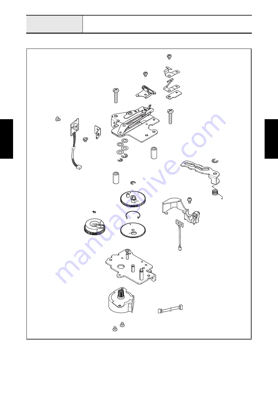
Страница 275: ...Application of Assembly 3 177 Feed module Application of Assembly Application of Assembly Feed module location diagram...

Страница 276: ...Shaft supporter 1 place MOLYKOTE EM30L Small amount 4 Vertical rod 1 place MOLYKOTE EM30L Small amount 5 1 place Oiler 1 to 2 drops 6 Lower shaft bushing 4 places FBK OIL RO 100 1 to 2 drops 7 Lower...

Страница 277: ...EPNOC AP N 0 Bead 12 Feed adjuster gear assy 1 place FBK OIL RO 100 1 to 2 drops 13 1 place EPNOC AP N 0 Rice grain size 14 Feed arm B assy 1 place FBK OIL RO 100 1 to 2 drops 15 Feed supporting plate...

Страница 278: ...he retaining ring E5 Set the set screw collar to the horizontal feed shaft and secure it with the screw set screw socket CP M4x4 while pushing the horizontal feed shaft to the left side 3 Align the bo...

Страница 279: ...ring E4 to the shaft of feed adjuster gear assy while pushing it to the right side 5 Set the set collar to the F initial shutter and set them to the shaft of feed adjuster gear assy Align the screw ho...

Страница 280: ...assy and then set the shaft bushing of FPM holder assy to the mounting position of base plate assy Attach the stopper plate to the base plate assy with the two screws screw bind M4x8 8 Set the spring...

Страница 281: ...E6 2 Tighten the two screws set screw socket CP M4x4 while pushing the set screw collar to the left side 3 Set the lower shaft bushing to the lower shaft B assy Key point Check that the set screw col...

Страница 282: ...ing plate assy 5 Align the two bosses of drop assy with the two positioning hole of base plate assy and attach the drop assy to the base plate assy with the two screws screw bind M4x5 Key point Check...

Страница 283: ...on 1 When the feed adjuster gear assy comes in contact with the lower shaft B assy and the gap between the F initial shutter and lower shaft B assy is 0 25 to 0 85 mm fully tighten the screw set screw...

Страница 284: ...Insert the two slide shafts A into the drop lever Q base plate assy and drop lever Q then attach the two retaining rings E2 to the two slide shafts A 2 Attach the vertical feed bush to the base plate...

Страница 285: ...bar assy to the feed arm assy with the two shafts and secure them with the two screws set screw socket CP M4x4 Key point Make sure that there is no gap at the right and left end of feed arm assy 3 At...

Страница 286: ...ket CP M4x6 temporarily 5 Set the feed dog to the feed bar assy and then tighten the two screws screw bind M3x6 temporarily Key point Fully tighten the screw after performing Adjustment of Front back...

Страница 287: ...bind M3x8 temporarily Key point Fully tighten the screw after performing Adjustment of Inner rotary hook bracket position 3 Attach the pile to the inner rotary hook assy and set the inner rotary hook...

Страница 288: ...Application of Assembly 3 190 Embroidery unit Application of Assembly Application of Assembly Embroidery unit location diagram...

Страница 289: ...XY pulse motor assy 2 places FBK OIL RO 100 1 to 2 drops 2 Driving pulley 10 places EPNOC AP N 0 Small amount 3 Y guide shaft 1 place MOLYKOTE M DISPERSION Thinly all surface 4 X guide shaft 1 place...

Страница 290: ...ully tighten the screw after performing Adjustment of Belt tension embroidery unit 2 Attach the X belt presser to the X carriage assy with the screw screw pan S P washer M4x8 Key point Press the timin...

Страница 291: ...B assy lead wire to the securing fixtures and bind up it to the main frame assy with the band Key point Refer to Wiring of Main frame assy 4 Connect the XPM lead wire assy to the XY pulse motor assy 5...

Страница 292: ...the retaining ring E3 2 Attach the X roller plate assy to the X carriage unit with the screw bolt socket S P washer M3x6 3 Attach the X carriage guide plate B cover to the X roller plate assy with th...

Страница 293: ...t presser plate and Y slider to the timing belt 40S2M862 with the screw screw pan S P washer M4x8 then engage the gullet of Y slider with the slider part of X carriage unit Key point Check that the ta...

Страница 294: ...main frame assy and it comes in contact with the two of those bosses shown as A Make sure that the another side of Y guide shaft is in between three bosses on the main frame assy 2 Slide the Y carria...

Страница 295: ...Attachment of Hole cover and Flexible flat cable SML2CD 6 1 Slide the Y carriage assy to come in sight of the hole 2 Attach the hole cover to the X carriage unit 3 Attach the X carriage cover rubber...

Страница 296: ...x6 Key point Refer to Wiring of Bending of Flexible flat cable SML2CD 6 6 Set the cord clip A to the flexible flat cable SML2CD 6 attach the cord clip A to the X carriage unit and set the cord clip B...

Страница 297: ...ing fixtures 2 Connect the lead wire assy YPM to the XY pulse motor assy and attach the XY pulse motor assy to the X carriage unit with the two screws screw pan S P washer M3x7 Key point Refer to Wiri...

Страница 298: ...and lock it Key point Refer to Wiring of Bending of Flexible flat cable SML2CD 7 and Wiring of X carriage unit Y relay PCB assy 4 Pass the flexible flat cable SML2CD 6 and flexible flat cable SML2CD 7...

Страница 299: ...ssembly 10 Attachment of Adjusting screw assy and ES base cover LID CW 1 Tighten the adjusting screw assy to the ES base cover assy two locations 2 Attach the ES base cover LID CW to the ES base cover...

Страница 300: ...of Assembly Application of Assembly 11 Attachment of X roller guide plate 1 Attach the X roller guide plate to the ES base cover assy with the three screws taptite cup B M4x14 Taptite Cup B M4X14 X r...

Страница 301: ...itch assy 2 Attach the CW switch assy to the ES base cover assy with the two screws taptite bind B M3x10 3 Set the lead wire assy cut work switch to the securing fixtures and attach the rubber to the...

Страница 302: ...chment of Lead wire assy EMB unit V 1 Set the EM connector holder and the lead wire assy EMB unit to the ES base cover unit and then secure them with the two screws screw pan washer M3x18 Screw Pan S...

Страница 303: ...Attach the ES base cover unit to the main frame assy with the two screws taptite cup B M4x14 Tighten the four screws screw pan S P washer M4x8 to the back of ES base cover unit Taptite Cup B M4X14 Sc...

Страница 304: ...CD 6 to the CN2 cut work switch assy lead wire to the CN6 X INIT PCB assy lead wire to the CN4 XPM lead wire assy to the CN3 and lead wire assy EMB unit to the CN1 Attach the relay PCB holder to the E...

Страница 305: ...n cover assy 3 Insert the each hook of ES main cover assy into the each hook tray of ES base cover unit and set the ES main cover assy to the ES base cover unit Tighten the six screws taptite cup B M4...

Страница 306: ...eck if the switch of frame sensor PCB assy works by moving E hoop lock lever 5 Align the positioning hole of E hoop pressure spring C with the boss of E hoop pressure plate and attach the E hoop press...

Страница 307: ...Y carriage assy with the two screws screw bind M4x6 Key point Refer to Wiring of X carriage unit Frame sensor PCB assy 2 Set the E hoop stay cover to the E hoop stay plate assy and secure it with the...

Страница 308: ...carriage cover and attach the X carriage cover to the X carriage unit with the screw screw pan T washer M4x8 2 Set the YPM cover to the X carriage cover slide the YPM cover to the direction of the ar...

Страница 309: ...Application of Assembly 3 211 Dual feed assy Application of Assembly Application of Assembly Dual feed assy location diagram...

Страница 310: ...taptite bind B M3x10 Set the extension code to the code bracket of the DF cover L 3 Put the DF belt on the gear 1 and 2 in this order and set the washer thrust2 two locations to the bushing 2 location...

Страница 311: ...n A below Key point Make sure that the joint bushing is lifted If it s at the bottom lift it up Refer to the section C below After assembling the DF cover R make sure that the belt end moves up and do...

Отзывы: