SAFETY AND MAINTENANCE MANUAL
1NO0024UK-09
71
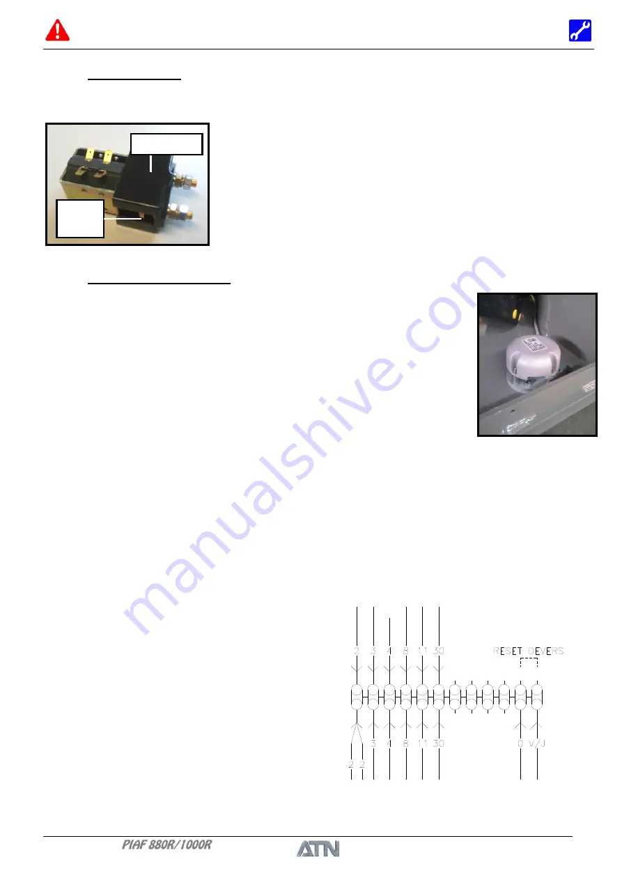
Mobile
part
Partie fixe
3.5. CONTACTOR
GENERALITIES
The power contactor is used to run the electric motor. It needs the
same upkeep as the motor. Regularly, it is necessary to clean by
blowing around the contacts. Check the state of surface of the
fixed and mobile parts of the contacts. Replace if necessary.
3.6. INCLINE DETECTOR
CONTROL PROCEDURE OF THE INCLINE DETECTOR
- place the machine on a slope of more than 2°.
- the buzzer of the alarm situated in the lower electrical box must be heard.
- the incline indicator situated on the upper box must be lit.
- the machine must be in 2
nd
speed.
- this means that the running is correct.
- NB -
This is just a control of the sound running of the incline detector - the adjustment must be
made on a test bench.
ADJUSTMENT OF THE ZERO REFERENCE POINT
When the rack is inclined at 2° to horizontal, the detector triggers the
buzzer and lights up the indicator light corresponding to the incline
situated on the upper control box. Moreover, the machine changes
automatically into second speed. The triggering of these alarm signals
indicates that the aerial work platform is reaching its stability limits.
It is therefore necessary to check this detector every day before any use
of the machine.
The system is supplied with standard
adjustment
and
configuration.
After
mechanical installation, it is important to
adjust the zero point, in other words to give
the system the new zero reference point.
Use a wire to bridge the 2 terminals (RESET
INCLINE), maintain the bridging until the
end of the blinking of the green LED
situated under the detector.
Fixed part
Содержание PIAF 1000R
Страница 2: ...SAFETY AND MAINTENANCE MANUAL 1NO0024UK 09 2 DISTRIBUTOR STAMP...
Страница 8: ...SAFETY AND MAINTENANCE MANUAL 1NO0024UK 09 8...
Страница 11: ...SAFETY AND MAINTENANCE MANUAL 1NO0024UK 09 11 Chapter I USE AND SAFETY...
Страница 12: ...SAFETY AND MAINTENANCE MANUAL 1NO0024UK 09 12...
Страница 16: ...SAFETY AND MAINTENANCE MANUAL 1NO0024UK 09 16...
Страница 22: ...SAFETY AND MAINTENANCE MANUAL 1NO0024UK 09 22...
Страница 34: ...SAFETY AND MAINTENANCE MANUAL 1NO0024UK 09 34...
Страница 36: ...SAFETY AND MAINTENANCE MANUAL 1NO0024UK 09 36...
Страница 37: ...SAFETY AND MAINTENANCE MANUAL 1NO0024UK 09 37 Chapter II MAINTENANCE...
Страница 38: ...SAFETY AND MAINTENANCE MANUAL 1NO0024UK 09 38...
Страница 62: ...SAFETY AND MAINTENANCE MANUAL 1NO0024UK 09 62 OK 1AU0080 01 2 6 HYDRAULIC DIAGRAM Diagram ref 1HY0026 01...
Страница 77: ...SAFETY AND MAINTENANCE MANUAL 1NO0024UK 09 77 3 13 ELECTRICAL DIAGRAM Diagram ref 1EL0023 01...
Страница 78: ...SAFETY AND MAINTENANCE MANUAL 1NO0024UK 09 78 NOTES...


