background image

QLS-3000/2000 Xe Series 

5-27 

Stepper Motor 

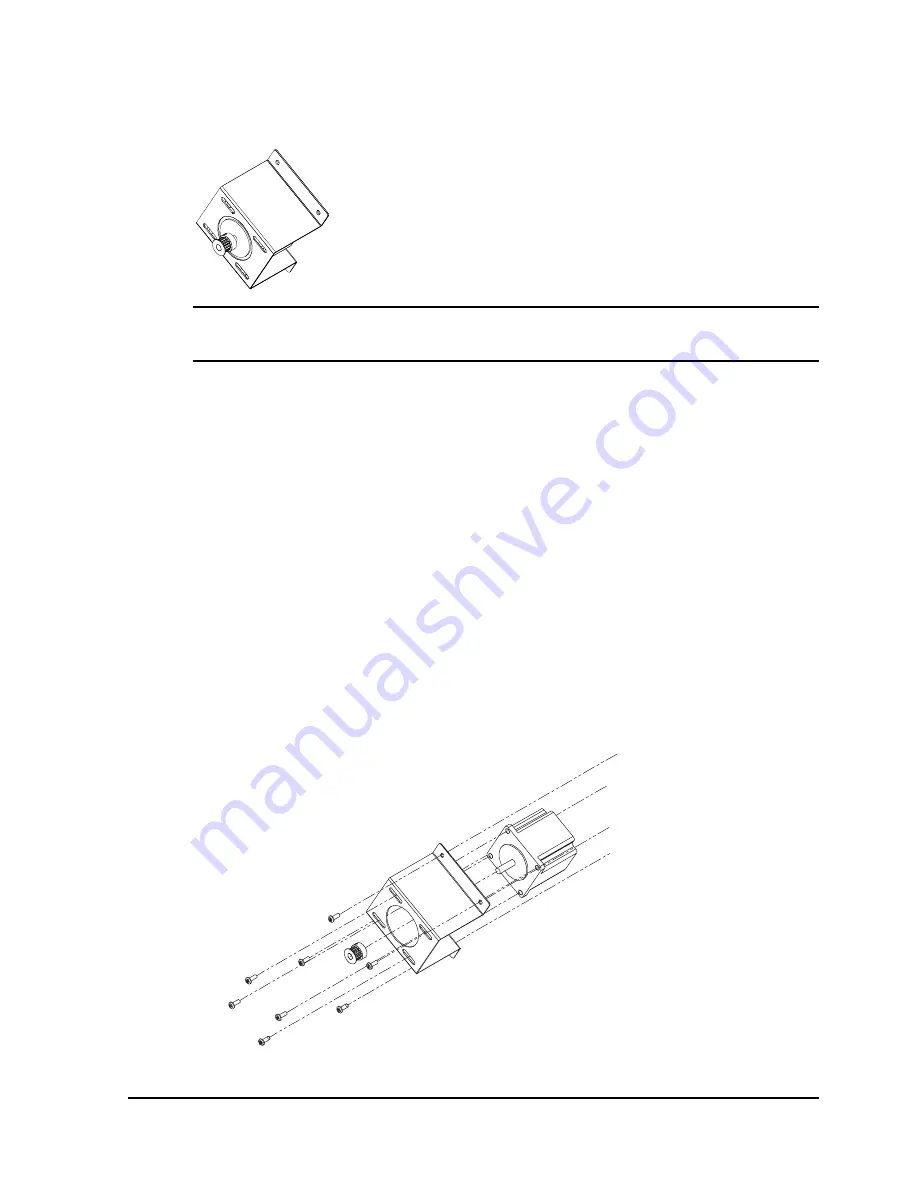
Use the following instructions to replace the stepper motor. 


Caution:

 Circuit boards can be damaged by static electricity. Always use 

standard anti-static procedures when working with these boards. 

To replace the stepper motor: 

1


Turn the printer off and unplug it.  Open the printer cover. 

2


Remove the back cover from the printer. 

3


Disconnect the stepper motor wire harness from the controller board. 
Note the location of the connector on the controller board. 

4


Remove the four Philips screws that connect the bracket to the main 
plate. Remove the bracket and motor from the printer. 

Note the position of the drive belt. You will need to install this belt later 
in this procedure. 

5


Remove the four adjustment screws to separate the stepper motor from 
the bracket. 


Содержание QLS-2000XE SERIES

Страница 1: ...tice ___________________________________________ QuickLabel Systems an Astro Med Inc Product Group 600 East Greenwich Ave West Warwick RI 02893 Tel 877 757 7978 Fax 401 822 2430 E mail info QuickLabel...

Страница 2: ...customer discovers a defect this defect must be reported promptly to QuickLabel Systems QuickLabel Systems will at its option repair or replace the defective component at no additional charge Repair p...

Страница 3: ...nty service call QuickLabel Systems Technical Support at 401 828 4000 or Toll Free in the USA and Canada at 877 757 7978 QuickLabel Systems An Astro Med Inc Product Group is not responsible for produc...

Страница 4: ...brook Quality Assurance Manager 05 02 2005 European Contact Your local Astro Med Inc Sales and Service Office FRANCE Astro Med SNC Parc d Activities de Pissaloup 1 rue Edouard Branly 78190 Trappes Tel...

Страница 5: ...onnection 2 6 Computer Connections 2 7 Parallel Port 2 7 RS 232 Serial Port 2 7 Communications 2 8 Printer Drivers 2 8 Comm Protocol 2 8 Comm Port 2 10 Baud Rate Handshaking 2 11 Utility Port Connecti...

Страница 6: ...m Menu 3 25 Port 3 25 Handshaking 3 26 Protocol 3 28 Prefix 3 29 Delimiter 3 30 System Menu 3 31 System Baseline 3 31 Upgrade 3 33 Language 3 34 Chapter 4 Printing 4 1 Printer Status 4 2 Initializatio...

Страница 7: ...29 Ribbon Rewind Motors 5 30 Microswitches 5 31 Ribbon Sensor 5 32 Fan 5 33 Boot PROM 5 34 Wiring Harnesses 5 34 Firmware Upgrades 5 35 Upgrading additional printers with the CompactFlash card 5 38 C...

Страница 8: ...DRIVE ROLL IS UP Close drive roll to resume printing 6 19 CUTTER FAULT Cutter motor stall or stacker is full 6 19 DRAM Error 6 21 Troubleshooting Procedures 6 22 Routine Cleaning 6 22 Loading Ribbon...

Страница 9: ...Series v Appendix A Physical Data A 1 Appendix B Specifications B 1 Appendix C Replacement Parts C 1 Appendix D Custom QuickLabel Setup D 1 Appendix E Windows Printer Driver Setup E 1 Appendix F Forma...

Страница 10: ...vi QLS 3000 2000 Xe Series...

Страница 11: ...e QLS 3000 Xe model prints full process color QLS 2000 Xe Prints two spot colors on top of the media QLS 2001 Xe Prints one spot color on each side of the media simultaneously QLS 3000 Xe Prints three...

Страница 12: ...it An MRC never locks you into purchasing media you don t want There is no minimum spending requirement no frequency requirement no advance payment and you may add new items at any time Freeze Your C...

Страница 13: ...the sequence listed below skipping over any items that may have been previously completed Page 2 2 Unpack the printer Page 2 6 Connect the AC power cord Page 2 7 Connect the host computer interface P...

Страница 14: ...1 4 Before You Get Started...

Страница 15: ...the printer before it can be operated This chapter provides the following information Instructions on unpacking and orienting the printer An overview of the features and components of the printer Inst...

Страница 16: ...f damage during shipment 3 Verify that the following items have been included in the packing carton AC Power Cord Centronics Parallel Cable IEEE 1284 Media Retainer Windows Printer Driver Diskette War...

Страница 17: ...rinter cover and five 6 screws shipped with the equipment Attach the cover to the printer Cutter Cutter Stacker or External Rewinder Peripherals are documented separately Refer to the documentation fo...

Страница 18: ...ewind mandrel front station 9 Guide roller 2 Thermal transfer ribbon tension switch 10 Print station cam lever open position 3 Thermal transfer ribbon unwind mandrel front print station 11 Printhead 4...

Страница 19: ...7 Drive roller 15 Media unwind mandrel 8 Platen roller Side Panel View Interface and power connections are located on the right side panel Utility Port Serial Port Parallel Port Memory Card Slot On Of...

Страница 20: ...bed in this chapter Warning Do not use any type of receptacle adapter or AC Power Cord that has not been supplied with the unit Doing so can result in damage to the printer Note The printer has been s...

Страница 21: ...the printer to as this will later be needed for driver or software setup Note The maximum recommended parallel cable length is 10 feet 3 m RS 232 Serial Port 1 Using a standard straight through connec...

Страница 22: ...To set the communications protocol and select a host command prefix 1 Press the MENU key Use the arrow keys to select Comm from the menu and then press the SELECT key 2 In the COMM menu use the arrow...

Страница 23: ...prefix is STX Press the SELECT key A confirmation message will appear on the display 9 Use the left right arrow keys to select YES then press the SELECT key 10 Pres the SELECT key again to return to...

Страница 24: ...communications If using RS 232 serial communications the printer uses 2 stop bits To select comm ports 1 Press the MENU key Use the arrow keys to select Comm from the menu and then press the SELECT k...

Страница 25: ...SELECT key Note The Baud Rate option is available only when RS 232 is used The Parallel port does not use this option 3 Use the left right arrow keys to select the Baud Rate option Use the up down arr...

Страница 26: ...rrow keys to select a handshaking method Hardware and XON XOFF are the available options Press the SELECT key A confirmation message will appear on the display 8 Use the left right arrow keys to selec...

Страница 27: ...otes 1 Reserved 2 Ground 3 Cutter On Off Output 1 on 0 off 4 5 VDC 1A max 5 Cutter Error Input 1 error 0 no error 6 Cutter Pulse 250 nsec pulse output 7 Reserved 8 Reserved 9 Error 5 1 9 6 Note If you...

Страница 28: ...inter Driver When using the QLS 3000 Xe with Process Color ribbons each of the print stations prints a dot pattern of a primary color Cyan Magenta or Yellow These primary colors overlap each other on...

Страница 29: ...as a guide 6 Advance the thermal transfer ribbon between the printhead and the platen roller 7 On standard printstations advance the thermal transfer ribbon over the thermal transfer ribbon guide spi...

Страница 30: ...nu allows you to tell the printer what type of media is loaded on the printer sensors image dimensions label dimensions and any offsets QLS 3000 Xe QLS 3001 Xe QLS 2000 Xe QLS 2001 Xe To load label me...

Страница 31: ...erclockwise on standard printheads clockwise on inverted printheads Standard Printhead Open Standard Printhead Closed Inverted Printhead Open Inverted Printhead Closed 3 Open the drive roller by flipp...

Страница 32: ...l other models thread media over the media index roller 8 On models with standard print stations thread the media over the platen rollers and under the guide rollers if present On models with inverted...

Страница 33: ...Continuous Media sensor detects no indicators Gap Media sensor interprets a gap slot or hole as a top of form indicator Inverted Gap Media sensor interprets a solid area as a top of form indicator Mar...

Страница 34: ...ad the printer is calibrated to detect the Media Out condition The printer s internal label queue is reset during calibration Any labels pending in the queue are terminated To calibrate the printer 1...

Страница 35: ...splayed is not the actual type loaded select No and return to step 4 6 Press the arrow keys to move the on display indicator to Yes then press Select The printer will perform an automatic calibration...

Страница 36: ...st the maximum label length Max Length Set this value to slightly more than the longest label you will be printing This setting allows the printer to use memory more efficiently 4 Use the left right a...

Страница 37: ...indicators and a multi function keypad The control panel permits the user to change settings and make adjustments on the fly without the need for a host computer This chapter provides the following in...

Страница 38: ...or continually advances the media when pressed and held CALIBRATE Calibrates the appropriate media sensor to the currently loaded media UP DOWN ARROW Cycles through settings within a menu and cycles...

Страница 39: ...s and System By choosing a top level menu and pressing the SELECT key you can scroll though functions related to the sub menu Pressing the SELECT key twice returns you to the current sub menu Pressing...

Страница 40: ...Memory Menu Total Displays the total amount of bitmap font and flash CompactFlash card memory Avail Displays the available amount of bitmap font and flash CompactFlash card memory Mode Menu Cutter Ac...

Страница 41: ...Menu Type Adjusts the type of media used by the printer Possible values are Continuous Gap Inverted Gap and Mark Image Adjusts the image width and length If label formatting software is used the width...

Страница 42: ...used Possible values are the printer name or Graphics Pref Selects the command and label format prefix for host commands received by the printer Delim Selects the delimiter for host commands received...

Страница 43: ...has 32 discrete heat settings A setting of 1 is the coolest setting resulting in the lightest print A setting of 32 is the hottest setting resulting in the darkest print The appropriate heat setting w...

Страница 44: ...ting from 1 coldest to 32 hottest for each printhead Press the up down arrows to increase decrease the heat intensity for the selected printhead Press the left right arrows to select a different print...

Страница 45: ...T menu use the arrow keys to select Previous Then press the Select key The name of the last printed label will be displayed If no label is stored in memory the text none will be displayed and the repr...

Страница 46: ...l Then press the Select key 3 Press the up down arrow keys to select the type of report to print Settings Prints a report of the current printer settings Data RXD Prints a report of the last 500 bytes...

Страница 47: ...down arrow keys to select the number copies to print To continuously run the pattern select the infinity symbol Press the SELECT key 5 Select Yes when prompted to overwrite memory with the test patter...

Страница 48: ...to 0 Select Cross Web and press the SELECT key Press the up down arrows to increase decrease the value for the selected printhead to 0 Press the left right arrows to select a different printhead Set...

Страница 49: ...Use the arrow keys to select Print from the menu and then press the SELECT key 2 In the PRINT menu use the arrow keys to select Speed Then press the Select key 3 Press the left right arrow keys to se...

Страница 50: ...emory it is erased when the printer is powered off Flash An external CompactFlash memory card can be used to store images or fonts This memory type is non volatile it remains saved when the printer is...

Страница 51: ...e MENU key Use the arrow keys to select Memory from the menu and then press the SELECT key 2 In the MEM menu use the arrow keys to select Avail The available amount of memory will be displayed MEM Tot...

Страница 52: ...cutter that will be used 4 If necessary press the left right arrow keys to select the Cut Flag option Use the up down arrow keys to enable disable the cut flag The Cut Flag option inserts extra blank...

Страница 53: ...mirror mode 1 Press the MENU key Use the arrow keys to select Mode from the menu and then press the SELECT key 2 In the MODE menu use the arrow keys to select Mirror Then press the SELECT key 3 Press...

Страница 54: ...elect TTR Sensor Then press the SELECT key Note The printhead names will vary based on the printer model 3 Press the up down arrows to turn the TTR Sensor on or off Use the left right arrows to move t...

Страница 55: ...ys to select Align from the menu and then press the SELECT key 2 In the ALIGN menu use the arrow keys to select Down Web Then press the SELECT key Note The printhead names will vary based on the print...

Страница 56: ...select Align from the menu and then press the SELECT key 2 In the ALIGN menu use the arrow keys to select Cross Web Then press the SELECT key Note The printhead names will vary based on the printer m...

Страница 57: ...has any top of form indicators and if so which type Continuous Media sensor detects no indicators Gap Media sensor interprets a gap slot or hole as a top of form indicator Inverted Gap Media sensor in...

Страница 58: ...1 Press the MENU key Use the arrow keys to select Media from the menu and then press the SELECT key 2 In the MEDIA menu use the arrow keys to select Image Then press the SELECT key 3 If necessary use...

Страница 59: ...e than the longest label you will be printing This setting allows the printer to use memory more efficiently 4 Use the left right arrow keys to select the Max Gap option Then use the up down arrow key...

Страница 60: ...up down arrow keys to set the print offset The print offset will affect the cut offset As a rule the print offset should be set first Print Offset Adjust the location of the printed image relative to...

Страница 61: ...cations If using RS 232 serial communications the printer uses 2 stop bits To select comm ports 1 Press the MENU key Use the arrow keys to select Comm from the menu and then press the SELECT key 2 In...

Страница 62: ...CT key Note The Baud Rate option is available only when RS 232 is used The Parallel port does not use this option 3 Use the left right arrow keys to select the Baud Rate option Use the up down arrow k...

Страница 63: ...own arrow keys to select a handshaking method Hardware and XON XOFF are the available options Press the SELECT key A confirmation message will appear on the display 8 Use the left right arrow keys to...

Страница 64: ...menu use the arrow keys to select Ptcl Then press the SELECT key 3 Use the up down arrow keys to select a protocol option Printer Name Select the printer name if you are printing via host commands Th...

Страница 65: ...3 Use the up down arrow keys to select a command prefix The default command prefix is SOH 4 Use the left right arrow keys to select the Fmt Prefix option Then use the up down arrow keys to select a fo...

Страница 66: ...In the COMM menu use the arrow keys to select Delim Then press the SELECT key 3 Use the up down arrow keys to select a command delimiter The default command delimiter is CR LF Press the SELECT key A c...

Страница 67: ...select System from the menu and then press the SELECT key 2 In the SYS menu use the arrow keys to select SysBase Then press the SELECT key 3 Press the up down arrow keys to increase decrease the syst...

Страница 68: ...l with the word TEST on each printer Assuming that 2 has the field in the correct location 1 would need a negative system baseline and 3 would need a positive system baseline After making the changes...

Страница 69: ...menu use the arrow keys to select Upgrade Then press the SELECT key 3 Use the up down arrow keys to choose Yes Then press the SELECT key The printer will perform a test and report the results on the...

Страница 70: ...arrow keys to select System from the menu and then press the SELECT key 2 In the SYS menu use the arrow keys to select Language Then press the SELECT key 3 Use the up down arrow keys to select a langu...

Страница 71: ...to the printer You have installed a software application from which you will print You have installed the QLS Windows Printer Driver as needed Once you have completed and verified the above you are re...

Страница 72: ...r is not in use leave printhead cams and the drive roller cam in the open position This will prevent flat areas from developing on the platen and drive rollers Current Settings To view status informat...

Страница 73: ...y 3 Press the up down arrow keys to select the type of report to print Settings Prints a report of the current printer settings Data RXD Prints a report of the last 500 bytes of data received by the p...

Страница 74: ...and ejecting the labels or tags by pressing the Pause key When a cutter or cutter stacker accessory is used in conjunction with the printer it is normal to have one tag cut shorter than normal and one...

Страница 75: ...color saturation If areas of white appear in a bar adjust heat intensity for that printhead You may also need to adjust printhead pressure Block The block test pattern is most useful to assess regist...

Страница 76: ...w keys to select Align from the menu and then press the SELECT key 2 Set the Down Web and Cross Web setting for each printhead to 0 Note The printhead names will vary based on the printer model Select...

Страница 77: ...e pattern examine alignment of the blocks within the pattern If registration is off on block edges or the pattern is not square realign the print stations On the QLS 3000 Xe the process black block sh...

Страница 78: ...e for use in specific applications Contact QuickLabel Systems Technical Support for more information To set heat intensity 1 Press the MENU key Use the arrow keys to select Intensity from the menu and...

Страница 79: ...clip 4 Cam lever The inner thumbwheel increases or decreases pressure on the inner half of the printhead The outer thumbwheel increases or decreases pressure on the outer half of the printhead Examine...

Страница 80: ...increase pressure on the selected printhead and darken the image 4 Slide the cam back in place Make sure the silver clip is securely seated 5 Flip the printhead cam closed to restore pressure to the...

Страница 81: ...han two inches wide tension may be excessive when the tension switch is in the High position If ribbons break flip the ribbon tension switch to Low Ribbon tension can also be adjusted on each individu...

Страница 82: ...CT key 3 Use the up down arrow keys to set the print offset The print offset will affect the cut offset As a rule the print offset should be set first Print Offset Adjust the location of the printed i...

Страница 83: ...lign from the menu and then press the SELECT key 2 In the ALIGN menu use the arrow keys to select Cross Web Then press the SELECT key Note The printhead names will vary based on the printer model 3 Pr...

Страница 84: ...u and then press the SELECT key 2 In the MODE menu use the arrow keys to select Mirror Then press the SELECT key 3 Press the up down arrows to enable disable Mirror mode Note Mirror mode must be enabl...

Страница 85: ...a 1 Press the MENU key Use the arrow keys to select Media from the menu and then press the SELECT key 2 In the MEDIA menu use the arrow keys to select Image Then press the SELECT key 3 If necessary us...

Страница 86: ...the arrow keys to select Print from the menu and then press the SELECT key 2 In the PRINT menu use the arrow keys to select Speed Then press the Select key 3 Press the left right arrow keys to select...

Страница 87: ...arrow keys to select Previous Then press the Select key The name of the last printed label will be displayed If no label is stored in memory the text none will be displayed and the reprint feature wi...

Страница 88: ...4 18 Printing...

Страница 89: ...nd trouble free operation In order to keep your printer operating at optimal performance some periodic maintenance is required This chapter provides the following information List of recommended tools...

Страница 90: ...n Clean printhead peel edge ribbon shafts platen rollers and drive roll at each change of ribbons Weekly Inspect drive roll and pressure roller for wear and residue buildup Clean ribbon and top of for...

Страница 91: ...relieve pressure Do not lock printheads into the up position 2 Press the silver clip holding each cam pull the cam completely out and set aside 1 Silver retaining clip 3 Cam lever 2 Outer thumbwheel...

Страница 92: ...ct to clean the printheads Damage will result if accumulated printing residue is scraped or chipped from the printhead Printer parts that accumulate the most residue are noted in the following illustr...

Страница 93: ...nthead Do not lock printheads into the up position 3 Press down the silver clip holding the printhead cam and pull the cam completely out To provide more maneuverability the printhead cam on the print...

Страница 94: ...inthead retaining plate 3 E ring washers securing platen roller 7 Center retaining screw 4 Platen support strut 9 Reinsert and tighten the printhead s captive retaining screw Be sure the cable harness...

Страница 95: ...down the silver clip holding the printhead cam s and pull the cam s completely out 5 Lift and hold the printhead assembly or assemblies completely up to the right With the platen roller now easily acc...

Страница 96: ...e a Philips head screwdriver to remove the bracket on the platen roller assembly 5 The platen roller on the inverted printhead is held in place by a bracket that is screwed over the assembly Use a Phi...

Страница 97: ...cover 2 Remove any label stock that may be exiting over the drive roller 3 Flip the drive roller cam up to relieve pressure on the roller and open it but do not lock into the open position 4 Press do...

Страница 98: ...ulls out 9 Insert the fresh drive roller making sure that the roller is fully inserted with the flat edge of the shaft coming in contact with the Allen screw 10 Replace the retaining plate lining up t...

Страница 99: ...ide the index assembly out through the rear side of the printer 6 Carefully remove the set screws on the encoder and slide it off the roller shaft A size 0 035 inch allen wrench is required for this s...

Страница 100: ...entally ensure the connector is oriented in the correct direction The five slots in the connector should be visible Use the following illustration as a guide 16 Position the index assembly so the medi...

Страница 101: ...f and unplug it Open the printer cover 2 Remove the back cover from the printer 3 Disconnect the two sensor harnesses from the media sensor assembly The harnesses are marked as P1 and RTOF Label each...

Страница 102: ...then tighten each screw This process ensures the sensor is mounted evenly 4 Plug in the new harnesses to the marked harnesses inside the printer 5 Re install the back cover 6 Plug in the printer and t...

Страница 103: ...etween the two numbers displayed when the calibration process has completed Reflective RTOF Sensor Adjustment 1 Load reflective media media with black band on the back into the printer 2 Block the sen...

Страница 104: ...F sensor with harness in its place 6 Calibrate the printer using the calibration procedure found earlier in the manual If the printer does not calibrate successfully adjustment to the RTOF sensor may...

Страница 105: ...d holes of the bracket Then remove the bracket 3 Slide the red plastic sensor molding away from the two sensor guides 4 Remove the top and bottom covers from the red plastic sensor molding Then remove...

Страница 106: ...sure the side with the red harness emitter is positioned on top of the clear harness detector 8 Reconnect the media sensor bracket to the assembly with the four flat head Phillips screws Ensure the re...

Страница 107: ...eplace a ribbon station anti static brush remove the two screws that secure the brush assembly to the main plate Then remove the two screws that secure the brush to the brush bracket Use the two screw...

Страница 108: ...to the peel edge then remove the brush Install the new brush with the two inch nuts ensuring the brush is facing the correct direction Ensure the brush makes contact with the ribbon Replace the print...

Страница 109: ...rom the printer Note the hole in the main plate that is used to feed the ribbon cable into the rear of the printer and use caution so the cable is not damaged 5 Turn the bottom plate upside down to ga...

Страница 110: ...board in the bottom plate with the ten nuts 10 Install the display board with the four screws The board must be oriented so the J2 harness is facing the associated connector Otherwise the harness will...

Страница 111: ...n disconnect all of the wiring harnesses from the controller board Note the orientation of the board This information will be helpful when installing the replacement board later in this procedure 4 Re...

Страница 112: ...Off QLS 2000 Xe Off On QLS 2001 Xe On On 7 Re install the back cover Connect all printer cables 8 Plug in the printer and turn the power on Note If you experience calibration problems after replacing...

Страница 113: ...rinter The power supply is located toward the front of the printer as indicated in the following illustration Power Supply 3 Disconnect harnesses P1 P2 P3 and P4 from the power supply 4 Remove the fou...

Страница 114: ...operating properly plug in the printer and turn the power on Then monitor the following voltages on the controller board 3 3V on T20 and T24 Ground 3 3V 1 1 V Printhead Voltage T23 and T24 Ground 25 7...

Страница 115: ...g it Open the printer cover 2 Remove the back cover from the printer 3 Disconnect the stepper motor wire harness from the controller board Note the location of the connector on the controller board 4...

Страница 116: ...ket to the main plate with four Philips screws 9 Position the drive belt over the pulley Then move the motor along the adjustment slots to create tension in the belt Tighten the adjustment screws to l...

Страница 117: ...the belt 4 Position the new drive belt over the stepper motor pulley Then move the motor along the adjustment slots to create tension in the belt Tighten the adjustment screws to lock the motor in po...

Страница 118: ...Remove the two Phillips screws and locking washers to disconnect the rewind motor assembly from the printer 5 Use the two Phillips screws with locking washers to install the new rewind motor assembly...

Страница 119: ...emove the back cover from the printer 3 Remove the two screws that secure the microswitch to the main plate Note the orientation of the microswitch Unplug the wire harness Note the orientation of the...

Страница 120: ...ug the wire harness from the ribbon sensor Note the orientation of the wire harness 4 Remove the two Phillips screws and locking washers from the ribbon sensor Note the orientation of the sensor and t...

Страница 121: ...from the printer 3 Remove the fan wire harness from the controller board The connector on the board will be marked as FAN 4 Remove the four screws from the fan and then remove the fan from the printer...

Страница 122: ...the printer The controller board is located toward the rear of the printer mounted on the main plate 3 Remove the boot PROM which is located in position U28 on the controller board Note the orientatio...

Страница 123: ...act on label production within your application Before beginning the upgrade process please verify the following The printer is powered on and is displaying Ready A CompactFlash card is installed in t...

Страница 124: ...el If necessary change the setup as required Remember to also configure the printer if necessary 4 Choose the Next button The following screen will appear The flash utility will query the printer to d...

Страница 125: ...n the file transfer All of the necessary files will be transmitted to the printer 6 When the file transfer is complete choose the Done or Cancel button on the display to exit the upgrade utility Upon...

Страница 126: ...er turn the power on and hold in the SELECT key on the front panel This sequence will place the printer into a forced upgrade mode The following menus will appear Insert the CompactFlash card that con...

Страница 127: ...g life and trouble free operation However occasional troubleshooting and printer adjustments may be required to correct printing problems This chapter provides the following information Printing probl...

Страница 128: ...ips for trouble shooting other types of missing print 1 Clean the printhead printline platen rollers and ribbon guide shafts See Routine Cleaning on page 6 22 2 Ensure the ribbon is loaded correctly S...

Страница 129: ...age 6 30 8 Replace the printhead See Replacing Printheads on page 6 30 9 Swap cables on the controller board from a known working printstation See Swapping Printhead Cables on page 6 32 10 Swap cables...

Страница 130: ...rint on 3 Try a different roll of ribbon 4 Try a different roll of labels tags 5 Ensure proper printhead intensities for the ribbon formulation being used See Selecting a Printhead Intensity on page 6...

Страница 131: ...on page 6 22 3 Ensure the ribbon is loaded correctly See Loading Ribbon on page 6 24 4 Ensure the labels tags are loaded correctly See Loading Label Tag Media on page 6 26 5 Increase the ribbon tensio...

Страница 132: ...ith the ribbon See Replacing Printheads on page 6 30 11 Try reducing the speed See Adjusting the print speed on page 6 39 12 Try rotating the image 180 degrees If this is an option for you it may help...

Страница 133: ...on is loaded correctly See Loading Ribbon on page 6 24 3 Reduce the ribbon tension See Adjusting Ribbon Tension on page 6 38 4 Reduce the printhead heat intensity on the print station that is breaking...

Страница 134: ...the rewind core If the ribbon is not rewinding properly on the rewind core it could cause ribbon drag or wrinkle Try removing all the ribbon from the rewind core and reload the ribbon 3 Reduce the pri...

Страница 135: ...and adjust the printhead angularity See Adjusting Printhead Angularity on page 6 43 3 Ensure the drive roller is not slipping If it is adjust the printhead pressure See Adjusting Printhead Pressure on...

Страница 136: ...original artwork and recreate the text and you are familiar with a graphics editing package you can utilize tools to clean up the image or text Eliminate anti aliasing and stray pixels Logo or Image...

Страница 137: ...e 6 46 2 Ensure the printer is properly calibrated for the material you are using See Calibrating the Printer on page 6 47 3 Ensure the labels tags are loaded correctly See Loading Label Tag Media on...

Страница 138: ...age 6 47 4 Ensure the sensor is clean of any adhesive build up See Cleaning the TOF Gap Sensor on page 6 51 5 Ensure the labels tags are not binding stalling at the drive roller If they are try decrea...

Страница 139: ...Enabling Disabling Printheads on page 6 29 6 Ensure proper ribbon match for the material you are trying to print on 7 Ensure the sensor is correctly positioned over the labels tags See Positioning the...

Страница 140: ...Try cables that you know are good A new cable is not necessarily a good cable 14 Ensure the Windows network or other network is not re directing the port to another printer or queue 15 Ensure the port...

Страница 141: ...ers and ribbon guide shafts See Routine Cleaning on page 6 22 4 Ensure the labels tags are loaded correctly See Loading Label Tag Media on page 6 26 5 Ensure all printheads that you want to use are en...

Страница 142: ...age 6 46 4 Ensure the printer is properly calibrated for the material you are using See Calibrating the Printer on page 6 47 5 Ensure the sensor is clean of any adhesive build up See Cleaning the TOF...

Страница 143: ...ure the sensor is clean of any adhesive build up See Cleaning the TOF Gap Sensor on page 6 51 5 Ensure the labels tags are not binding stalling at the drive roller If they are try decreasing the drive...

Страница 144: ...age 6 38 3 Ensure there is no excessive printhead pressure See Adjusting Printhead Pressure on page 6 35 4 Ensure the sensor is clean of any adhesive build up See Cleaning the TOF Gap Sensor on page 6...

Страница 145: ...n CUTTER FAULT Cutter motor stall or stacker is full 1 Ensure the cutter blade safety cover is securely in position over the cutter blade The end of the cover must go into the hole where the switch is...

Страница 146: ...When the tray fills up it activates the stacker full switch and gives the Cutter Stall or Stacker Full message Empty the tray and continue printing 3 Ensure the cable connecting the cutter section to...

Страница 147: ...QLS 3000 2000 Xe Series 6 21 DRAM Error 1 Try rebooting the printer cycle the power 2 The CPU board may need repair or replacement...

Страница 148: ...am open to relieve pressure Do not lock printheads into the up position 2 Press the silver clip holding each cam pull the cam completely out and set aside 1 Silver retaining clip 3 Cam lever 2 Outer t...

Страница 149: ...bject to clean the printheads Damage will result if accumulated printing residue is scraped or chipped from the printhead Printer parts that accumulate the most residue are noted in the following illu...

Страница 150: ...bon roll on the thermal transfer ribbon unwind mandrel Ensure that the ribbon unwinds to the left of and beneath the roll 3 Fully seat a cardboard take up core on the associated thermal transfer ribbo...

Страница 151: ...8 On standard printstations advance the thermal transfer ribbon beneath and around the cardboard take up core on the rewind mandrel On inverted printstations advance the thermal transfer ribbon above...

Страница 152: ...enu allows you to tell the printer what type of media is loaded on the printer sensors image dimensions label dimensions and any offsets QLS 3000 Xe QLS 3001 Xe QLS 2000 Xe QLS 2001 Xe To load label t...

Страница 153: ...erclockwise on standard printheads clockwise on inverted printheads Standard Printhead Open Standard Printhead Closed Inverted Printhead Open Inverted Printhead Closed 3 Open the drive roller by flipp...

Страница 154: ...ll other models thread media over the media index roller 8 On models with standard print stations thread the media over the platen rollers and under the guide rollers if present On models with inverte...

Страница 155: ...simply lock the printhead in the closed position Standard Printhead Closed Inverted Printhead Closed Disable Make sure the printhead s that you do not want to use are opened when you turn the printer...

Страница 156: ...Do not lock printheads into the up position 3 Press down the silver clip holding the printhead cam and pull the cam completely out To provide more maneuverability the printhead cam on the print statio...

Страница 157: ...etaining plate 3 E ring washers securing platen roller 7 Center retaining screw 4 Platen support strut 9 Reinsert and tighten the printhead s captive retaining screw Be sure the cable harness is not c...

Страница 158: ...ntroller board as stated below By unplugging the harness on the controller board and plugging it into a different connector on the same board you can determine if the problem is in the print station o...

Страница 159: ...ess of the print The amount of heat that is actually applied to the film by the printhead is determined by two factors Length of time that power is applied to the printhead Rate at which the media is...

Страница 160: ...that requires more heat to produce a satisfactory image is less advantageous in terms of speed and performance than higher quality media that images easily and quickly at lower temperatures If you us...

Страница 161: ...ining clip 4 Cam lever The inner thumbwheel increases or decreases pressure on the inner half of the printhead The outer thumbwheel increases or decreases pressure on the outer half of the printhead E...

Страница 162: ...the printhead and lighten the image Turn thumbwheels clockwise to lower them increase pressure on the selected printhead and darken the image 4 Slide the cam back in place Make sure the silver clip i...

Страница 163: ...e bolt securing the platen strut and tap the strut backward to adjust the position of the platen roller The platen roller for the color indicated by 3 is too far behind the printhead Loosen the bolt s...

Страница 164: ...inches wide tension may be excessive when the tension switch is in the High position If ribbons break flip the ribbon tension switch to Low Ribbon tension can also be adjusted on each individual print...

Страница 165: ...s the MENU key Use the arrow keys to select Print from the menu and then press the SELECT key 2 In the PRINT menu use the arrow keys to select Speed Then press the Select key 3 Press the left right ar...

Страница 166: ...but do not lock Press down the silver clip holding the printhead cam s and pull the cam s completely out 5 Lift and hold the printhead assembly or assemblies completely up to the right With the platen...

Страница 167: ...Use a Philips head screwdriver to remove the bracket on the platen roller assembly 5 The platen roller on the inverted printhead is held in place by a bracket that is screwed over the assembly Use a P...

Страница 168: ...aligning all images on both sides of the media for narrow two sided printing 1 Create a cross in the center of the label on both pages 1 and 2 Make these lines the color of the front print station Re...

Страница 169: ...bracket on each print station Loosen the center philips screw on the print station that needs adjustment and move the printhead bracket forward or backwards to line it up with the other colors 3 Repe...

Страница 170: ...nter cover 2 Remove any label stock that may be exiting over the drive roller 3 Flip the drive roller cam up to relieve pressure on the roller and open it but do not lock into the open position 4 Pres...

Страница 171: ...pulls out 9 Insert the fresh drive roller making sure that the roller is fully inserted with the flat edge of the shaft coming in contact with the Allen screw 10 Replace the retaining plate lining up...

Страница 172: ...g labels with gaps between them or directly over the notch or hole punch 1 Pointer 2 Red slider Confirm that the gap notch string hole or punchout is aligned with the pointer on top of the media gap s...

Страница 173: ...e last calibrated values and menu setups even after shut down and restart When calibrating continuous media media length cannot be calibrated Instead the printer is calibrated to detect the Media Out...

Страница 174: ...of form indicator Inverted Gap media sensor interprets a solid area as a top of form indicator Mark media sensor interprets a dark reflective mark as a top of form indicator 5 Press Calibrate Confirm...

Страница 175: ...o select System from the menu and then press the SELECT key 2 In the SYS menu use the arrow keys to select SysBase Then press the SELECT key 3 Press the up down arrow keys to increase decrease the sys...

Страница 176: ...h the word TEST on each printer Assuming that 2 has the field in the correct location 1 would need a negative system baseline and 3 would need a positive system baseline After making the changes the l...

Страница 177: ...housing Use alcohol to clean any build up you may see Use compressed air and direct it between the sensor s top and bottom bracket The reflective sensor is mounted facing upward on the inside portion...

Страница 178: ...elect Graphics if you are printing via the Windows driver Press the SELECT key A confirmation message will appear on the display 4 Use the left right arrow keys to select YES then press the SELECT key...

Страница 179: ...key 10 Pres the SELECT key again to return to the COMM menu 11 In the COMM menu use the arrow keys to select Delim Then press the SELECT key 12 Use the up down arrow keys to select a command delimiter...

Страница 180: ...the fuse Changing the Fuse Voltage The fuse size varies from 220 VAC to 110 VAC To change from 110 VAC to 220 VAC remove the existing fuse from the fuse holder Then turn the holder upside down remove...

Страница 181: ...QLS 2000 3000 Xe Series A 1 Appendix A Physical Data...

Страница 182: ...A 2 Physical data QLS 2000 3000 Xe Series Dimensions 22 000 19 640 All dimensions are in inches...

Страница 183: ...QLS 2000 3000 Xe Series A 3 QLS 2000 3000 Xe Series Dimensions 17 032 4 289 2 644 1 250 All dimensions are in inches...

Страница 184: ...A 4 Physical data...

Страница 185: ...QLS 3000 2000 Xe Series B 1 Appendix B Specifications...

Страница 186: ...iver 22 55 9 cm with Custom QuickLabel Fonts 7 TrueType fonts resident other TrueType fonts can be downloaded from your PC Resident Barcodes All Standard symbologies including 2 Dimensional Control Pa...

Страница 187: ...irements 110 240 VAC 50 60 Hz 400W Thermal Transfer Ribbon Number of rolls varies based on number of print stations Each roll 300 m long Spot or CMYK rolls Label Tag Size Width 4 625 117 mm Max 1 25 m...

Страница 188: ...B 4 Specifications...

Страница 189: ...QLS 3000 2000 Xe Series C 1 Appendix C Replacement Parts...

Страница 190: ...Roller Kit black silicone 70 75 Dur 26395 600 Platen Roller Kit white silicone 60 Dur 26390 600 Platen Roller Kit brown polyurethane 60 Dur Hang Tags 26390 700 Platen Roller Kit clear green polyuretha...

Страница 191: ...requires 035 Allen wrench 25123 000 Sensor Optical Encoder 25748 000 Sensor Harness TOF 24816 000 Sensor Harness RTOF 26183 100 Micro Switch Harness Assy 1 station 11461 000 Switch Interlock only 4277...

Страница 192: ...C 4 Replacement parts...

Страница 193: ...QLS 3000 2000 Xe Series D 1 Appendix D Custom QuickLabel Setup...

Страница 194: ...s for an upgrade To configure Custom QuickLabel from Create and Print Note Skip to step 4 if you are configuring the Print application Steps 1 3 are for configuring a new or existing label format in t...

Страница 195: ...Setup menu The following screen will appear 5 Choose your printer from the Select Printer pull down list If you are using the QLS 3001 Xe printer select single sided or double sided 6 Click on the Co...

Страница 196: ...he QuickLabel Systems Windows Printer Driver must be installed to use this communication mode Print to File This communication method is used to generate ASCII label format files and binary image font...

Страница 197: ...QLS 3000 2000 Xe Series E 1 Appendix E Windows Printer Driver Setup...

Страница 198: ...Faxes Windows XP Right click on the QLS 3000 2000 Xe Series Windows printer driver and select Properties The driver properties window will be displayed If you are using Windows XP or 2000 choose the...

Страница 199: ...e A representation of the output effect each halftoning method will have is shown to the right Generally speaking Coarse Medium and Fine work best for line art and vector based graphics such as clip a...

Страница 200: ...o enable or disable each of the print stations by checking or unchecking the box next to each head Click on the Change button to specify the color corresponding to your artwork that will be printed on...

Страница 201: ...turn to the Properties window 6 Click on the Ports tab Select the appropriate communication port that the printer is connected to from the pull down list of available ports 7 Click on the Device tab I...

Страница 202: ...ensity Print Speed Quantity and Offsets just prior to printing You may choose to display a full Print Time menu the default or one which allows entry of print quantity only 8 When the Print Time menu...

Страница 203: ...From the menu select File Save Processed Image As 2 In the Save As window that appears enter a filename for the processed label Place a check mark in the Place shortcut on Desktop box if you would lik...

Страница 204: ...E 8 Windows printer driver setup...

Страница 205: ...QLS 2000 3000 Xe Series F 1 Appendix F Format Error Codes...

Страница 206: ...character height error Valid settings for font height are 10 to 2000 for TrueType fonts and 1 to 10 for bitmap fonts 6 Alphanumeric character width error The range for width values is the same as for...

Страница 207: ...or The AF command contains an invalid write method parameter must be 1 20 Format command error The structure of one or more label format commands is faulty Some examples would be misplaced or missing...

Страница 208: ...cified Valid field colors range from 1 to 15 41 Print disable command error Print disable command contains invalid parameters STX PD 80 PCX Bitmap scale error Valid scale factors for PCX graphics fiel...

Страница 209: ...eld Data command STX FE This error results from any of the following Too much data barcode font Bar code field strings contain characters not supported by the chosen symbology 88 PDF417 security level...

Страница 210: ...F 6 Format error codes...

Страница 211: ...Roller Replacement 5 9 6 44 Drivers 2 8 Error Messages 6 17 Field Position 6 11 Firmware Upgrade 5 35 Flood Test Pattern 4 5 Fuse 6 54 Gap Media 2 19 3 21 Handshaking 2 11 3 26 Handshaking Menu 3 26...

Страница 212: ...12 Print Position 4 12 Print Quality 4 5 Print Speed 4 16 6 39 Print Pause 4 4 Printer Status 4 2 Printhead Angularity 6 43 Pressure 6 35 Printhead Cables 6 32 Printhead Enable Disable 6 29 Printhead...

Страница 213: ...age 3 34 System Baseline 3 31 Upgrade 3 33 Test Menu 3 11 Test Patterns Block 4 5 Flood 4 5 Line 4 5 Printing 4 5 Text 4 5 Text Test Pattern 4 5 TOF Gap Sensor Cleaning 6 51 Positioning 6 46 Total Mem...

Страница 214: ...iv Index...

Отзывы: