Manual of Weighing Controller A 810
Page
14
A.S.T. Angewandte SYSTEM-TECHNIK GmbH Dresden
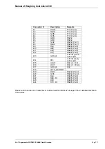
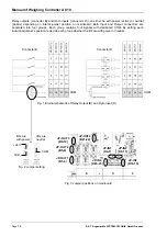
Relay outputs (connector B) and Opto inputs (connector D) can either be with power (active) or neutral
(passiv) depending on interal jumper position on mainboard. Both Input and Output connectors are
separated into four groups. Each group contains four signals with dedicated COM. By setting each
individual jumper’s position to decide each group whether the I/O are with power or neutral.
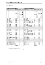
JP-OUT1
(B1-4)
B
D
E
Fig. 3 Jumper positions on mainboard
JP- OUT2
(B5-8)
JP- OUT3
(B9-12)
JP-OUT4
(B21-24)
JP-IN4
(D20-23)
JP-IN1
(D4-7)
JP-IN2
(D8-11)
JP-IN3
(D16-19)
Fig. 1 Internal schematic of Relay Output (B) and Opto Input (D)
Fig. 2 Jumper setting
Connector B
Connector D
+24V
Gnd
COM
COM
COM
I/Os are
I/Os are
with power
neutral


