


AT32F425
Series Reference Manual
2022.03.30
Page 353
Ver 2.01
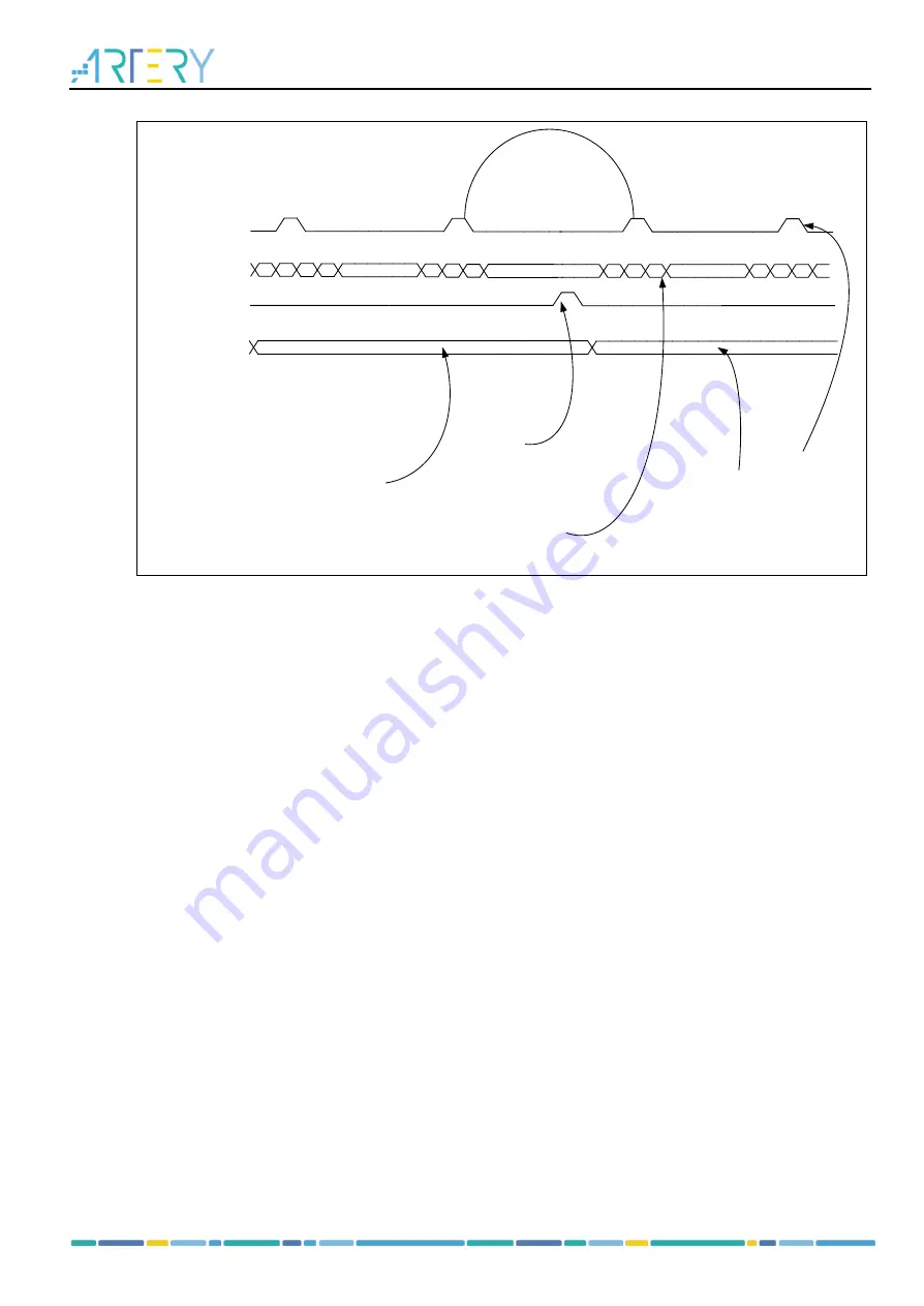
Figure 20-6 HFIR behavior when HFIRRLDCTRL=0x1
SOF
HFIR DN
Counter
Application Load
Of HFIR
HFIR
1
0 400 399
1
0 400
********************
********************
1
450
0
******************** 1
450
0
499
(1)Old HFIR Value
(2)HFIR Reloaded
(3)SOF Lost
Synchronization NOT
Lost Due to HFIR
Reload
(4)HFIR Counter
restarts after
completing previous
count
(5)New HFIR Value
(6)SOF back in
Synchronization
400
450
The sequence of operation is as follows:
1.
After power-on reset, the current HFIR value set by the application is shown
2.
The application loads a new HFIR value; the HFIR counter does not apply this new value, but
continues counting until it reaches 0
3.
The counter generates a SOF when it reaches 0 using the old HRIF value
4. the HFIR counter applies a new value
5. New HFIR value takes effect
The SOF synchronization resumes after going through above-mentioned stpes.
20.5.3.7 Initialize bulk and control IN transfers
shows a typical bulk or control IN transfer operation. Refer to channel 2 (ch_2) for more
information. The assumptions are as follows:
The application is attempting to receive two largest-packet-size packets (transfer size is 64
bytes)
The receive FIFO contains at least one largest-packet-size packet and two status DWORDs per
each packet (72 bytes for full-speed transfer)
The non-periodic request queue depth is 4
(
1
)
Operation process for common bulk and control IN transfers
The sequence of operations shown in Figure 21-7 is as follows:
1.
Initialize channel 2 (according to OTGFS channel initialization requirements)
2.
Set the CHENA bit in the OTGFS_HCCHAR2 register to write an IN request to the non-periodic
request queue
3.
The controller issues an IN token after completing the current OUT transfer
4.
The controller generates a RXFLVL interrupt as soon as the receive packet is written into the receive
FIFO
5.
To handle the RXFLVL interrupt, mask the RXFLVL interrupt and read the received packet status to
determine the number of bytes received, and then read the receive FIFO. Following this step to
unmask the RXFLVL interrupt
6.
The controller generates the RXFLVL interrupt when the transfer complete status is written into the


