background image

Chapter 3    Supplementary Operations

AE-4022   

3-16

4

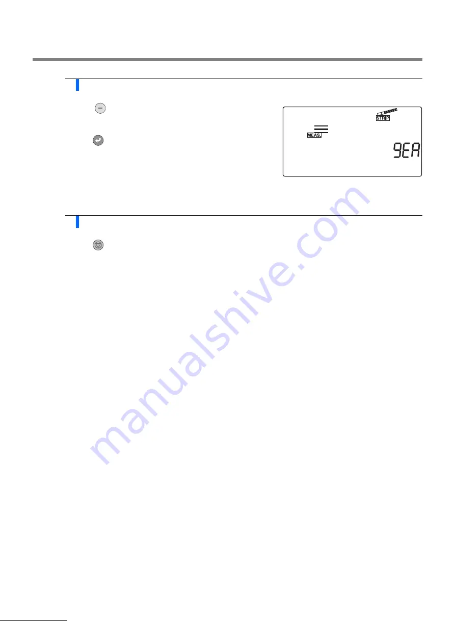
Select which test strip to use

a

Using 

, select the test strip type to be used in the current 

measurement mode.

b

Press  

.

• The test strip type is confirmed, and the display returns to the 

[Menu screen].

5

Quit the STRIP setup menu

a

Press  

.

• The display returns to the [Standby screen].

Содержание AUTION ELEVEN AE-4022

Страница 1: ......

Страница 2: ...ual thoroughly before using the instrument This operating manual gives an outline of the system and the proper procedures for operation maintenance and troubleshooting Follow the instructions in the manual in order to maintain the instrument warranty 2015 ARKRAY Inc It is strictly prohibited to copy any part of this reference manual without the expressed consent of ARKRAY Inc ...

Страница 3: ...ol xvi Limitations xvi Chapter 1 Before Using the AE 4022 1 1 1 1 Outline of the AE 4022 1 2 1 1 1 AE 4022 Features 1 2 1 1 2 Measurement types 1 4 1 1 3 Specifications 1 5 1 2 Name and function of each part 1 6 1 2 1 Front side 1 6 1 2 2 Rear side 1 7 1 2 3 Display 1 8 1 2 4 Operator panel 1 10 1 3 Installing the instrument 1 11 1 3 1 Precautions for installation 1 11 1 3 2 Installation of the in...

Страница 4: ...enu screen 3 2 3 1 1 How to operate the menu screen 3 2 3 1 2 Menu list 3 3 3 2 MODE measurement mode selection 3 4 3 3 MEMORY reprinting and resending measurement results 3 6 3 4 DATE setting the date and time 3 11 3 5 LIST printing a list of abnormal measurement results 3 13 3 6 STRIP selecting the test strip type 3 15 3 7 SETUP user settings 3 17 3 7 1 Operation of user settings 3 17 3 7 2 List...

Страница 5: ... 3 47 3 7 23 No 021 QC lock out function ON OFF 3 50 3 7 24 No 022 Clarity input function ON OFF 3 52 3 7 25 No 090 Printing of a trouble list 3 53 3 7 26 No 099 Initialization of parameters 3 54 Chapter 4 Maintenance 4 1 4 1 Daily maintenance 4 2 4 1 1 Cleaning the feeder 4 2 4 1 2 Cleaning the waste box 4 10 4 2 Replacing the thermal recording paper 4 12 4 3 Maintenance of the instrument when it...

Страница 6: ...r the determination of a particular analyte The chemical reaction with the urine results in a color change and indicates the concentration of the analyte The AUTION ELEVEN AE 4022 technology provides fast results that can be used along with other diagnostic information to rule out certain disease states and to determine if microscopic analysis is needed There are substances that may interfere with...

Страница 7: ...ctance of the given wavelength off of each individual pad as an indicator of analyte concentration To reduce lot to lot and device to device variability in the instrument and test strips additional design features were added To mitigate variability in the cumulative factors affecting light measured the infrared wavelength 760 nm is also directed at every pad except blood to be used as a reference ...

Страница 8: ... measurements temperature corrections are applied as follows Lastly the calibration curve algorithm takes a history of device model and technology comparison data into consideration and converts the reflectance into qualitative symbols and semi quantitative values for widespread usability The chemical principles common names of the test strip reagents and their compositions can be found on the AUT...

Страница 9: ...ts detected presence in urine indicates the disruption or an increase in hemoglobin catabolism Intestinal bacteria can turn bilirubin into urobilinogen It can be an early indicator of liver disease or jaundice Causes of increased urinary bilirubin and urobilinogen include prehapatic increased heme degradation due to a transfusion reaction sickle cell disease hereditary spherocytosis thalassemia pe...

Страница 10: ...ract infections With early intervention the spread of infection to the kidneys and possible development of renal failure can be prevented Screening does not replace the urine culture for the identification and quantification of bacteria but it can rapidly identify patients with asymptomatic bacteriuria for minimal expense Leukocytes white blood cells Significant numbers of white blood cells indica...

Страница 11: ... of strong electromagnetic radiation as these may interfere with the proper operation Caution in Handling Specimens BE CAREFUL WHEN HANDLING URINE This system uses urine as sample and as an ingredient of Control Urine may be contaminated by pathogenic microorganisms that can cause infectious diseases Improper handling of urine may cause infection to the user or other individuals by pathogenic micr...

Страница 12: ...inch points Follow the instructions given here to prevent burns from hot surfaces To avoid Damage to the Product or its Performance IMPORTANT Follow the instructions given here to obtain accurate measurement results NOTE Information useful for preventing damage to the instrument or parts and other important information you should keep in mind REFERENCE Additional explanations that help you make th...

Страница 13: ...the carrying arm is moving do not put your hand close to the arm so as to avoid being caught or pinched Never touch with unprotected hands the carrying arm where the sample may adhere During cleaning or maintenance of the carrying arm wear protective gloves to prevent exposure to pathogenic microorganisms Never touch with unprotected hands the maintenance cover and inside the instrument where the ...

Страница 14: ...e may adhere During cleaning or maintenance of the waste box wear protective gloves to prevent exposure to pathogenic microorganisms e Do not touch the motor and its surrounding area which may be hot and cause burn on the hand especially during operation and just after the instrument is turned off ...

Страница 15: ...mportant as the technical performance of urinalysis Acceptable specimens improve the quality and reliability of urinalysis results CLSI Guidelines should be followed Collection should be clean and opaque containers should be used to protect the specimen from light Specimens should be used within 2 hours or refrigerated Relevant information should be recorded for the physician regarding specimen co...

Страница 16: ... See below 1 No Name Description Qty a Test strip tray 1 b Check strip set 2 check strips white 1 c Thermal recording paper 58 mm width 5 rolls 1 d AC adapter 1 e Power cord 1 f Operating manual 1 a Instrument b Accessory kit box a Test strip tray b Check strip set c Thermal recording paper d AC adapter e Power cord f Operating manual ...

Страница 17: ...should be confirmed regularly utilizing both known negative and known positive urine specimens or control materials Adhere to all regulations applicable to the practice region as well as manufacturers instructions Refer to 2 4 3 Control measurement on page 2 27 for specific instructions Limitations Please refer to the AUTION Sticks 10EA package insert for information on any limitations and interfe...

Страница 18: ... 1 4 1 1 3 Specifications 1 5 1 2 Name and function of each part 1 6 1 2 1 Front side 1 6 1 2 2 Rear side 1 7 1 2 3 Display 1 8 1 2 4 Operator panel 1 10 1 3 Installing the instrument 1 11 1 3 1 Precautions for installation 1 11 1 3 2 Installation of the instrument 1 12 1 3 3 Starting and ending operation after installation 1 16 ...

Страница 19: ... seconds at its maximum speed thus enabling a maximum system output of 514 samples per hour Measurement auto stop When the instrument detects that no test strip is placed on the test strip tray it automatically stops measurement Auto start and non directional test strip placement The instrument automatically detects a test strip when placed on the test strip tray and starts measurement Measurement...

Страница 20: ...quired to set up the QC lock out function Clarity input function This function allows the operator to manually input the value of urine clarity obtained visually in order to add it to the measurement results report This instrument does not have a function to automatically determine urine clarity When the Operator ID function is ON the access authority to the SETUP menu is required to set up the cl...

Страница 21: ...er the measurement number of the first STAT sample is entered the system automatically increments the STAT measurement number by one for each subsequent measurement When measuring another batch after returning to the Standby screen see Note below the system continuously allocates consecutive STAT Nos until the instrument is turned OFF Control measurement The Control measurement mode is used for th...

Страница 22: ... Conforms to RS 232C standard serial Option Ethernet Memory capacity 520 measurement results Operating environment Temperature 50 to 86 F 10 to 30 C Humidity 20 to 80 R H non condensing Measurement environment Temperature 50 to 86 F 10 to 30 C Humidity 30 to 60 R H non condensing Temperature correction function used Storage environment Temperature 33 8 to 86 F 1 to 30 C Humidity 20 to 80 R H non c...

Страница 23: ...aintenance cover f Test strip tray Place the test strip on this tray after dipping it in the sample to be measured g Carrying arm Carries the test strip placed on the test strip tray to the suction ports while the tray rails adjust the position h Suction ports They absorb surplus sample urine adhering to the test strip i Test strip feed mechanism Transfers the test strips to the photometric sectio...

Страница 24: ...minal For connection with the supplied AC adapter c B C R Terminal for the optional hand held barcode reader d RS 232C Terminal for an external device Ethernet optional For connection to an Ethernet unit e Waste box Used test strips are discarded in this box f Printer cover Open this cover to replace the thermal recording paper e a f b c d ...

Страница 25: ...rement mode Different information is displayed depending on the present measurement operation operational status and menu c Test strip type The test strip type for the current setting is displayed In the check measurement mode the current time is displayed To set the test strip type see 3 6 STRIP selecting the test strip type on page 3 15 No Name Function a Menu icon area Area for menu icons Press...

Страница 26: ...ments and while Control measurement settings are changed 3 4 CHECK icon Selected to perform CHECK measurement This icon appears during CHECK measurements and while CHECK measurement settings are changed 3 4 ID icon Appears when a patient ID number is input or displayed 3 8 No icon Appears when a measurement number is input or displayed Also appears while an item number is entered or displayed when...

Страница 27: ...o the built in printer while this key is pressed MENU Press to move between menus or to change pages ENTER This Enter key selects a menu or item to be set or confirms the input value hyphen Press to select an item to be set or to input a hyphen character 0 to 9 numeric keys Use these numeric keys to select a menu or to input values ID Press before inputting a patient ID number Left right Press to ...

Страница 28: ...rument resulting in personal injury Do not install the instrument where it may fall off or topple over Do not install the instrument near places that store chemicals or near equipment that generates corrosive gas or electrical noise Chemicals corrosive gases and electrical noise may cause fire or damage to the instrument and consequently lead to personal injury or may otherwise cause incorrect mea...

Страница 29: ...ying arm and connection cable sold separately when communicating with an external device 1 Release the carrying arm and maintenance cover aRemove the fixing tapes from the carrying arm and maintenance cover 2 Open the maintenance cover aPress and hold the two cover open buttons on either side of the instrument at the same time 1 in the right figure and open the maintenance cover 2 in the right fig...

Страница 30: ...fixing tape from the suction ports 4 Close the maintenance cover aClose the maintenance cover until it clicks closed Fixing tape Suction ports NOTE After removing the fixing tape press the suction ports with your finger and ensure that the part is securely fixed in its proper position ...

Страница 31: ...k of the instrument 7 Connect the power cord aConnect the power cord to the AC adapter bCheck that the power switch at the back of the instrument is in the OFF position the side of the ON OFF switch should be visible cConnect the AC adapter to the power input terminal on the back of the instrument and connect the plug of the power cord to a wall outlet Fixing tape Fixing tape Power cord AC adapter...

Страница 32: ...cable ensure that an optional Ethernet unit is attached to the instrument then connect the cable to the unit s LAN port 9 Connect a handheld barcode reader if necessary aTo use an optional handheld barcode reader connect the B C R cable to the instrument s B C R terminal REFERENCE Use an appropriate connection cable option when connecting an external device Cable RS 232C LAN cable Port Ethernet un...

Страница 33: ... approximately 1 second cThe product name and system version 1 00 in the right figure are displayed on the screen and the system starts a self diagnosis routine after approximately 2 seconds The backup memory is checked for any abnormality dThe time is counted down for 20 seconds until the initialization of each mechanism in the instrument is completed During the countdown the carrying arm repeats...

Страница 34: ...to 3 4 DATE setting the date and time on page 3 11 NOTE An error or problem is indicated by a buzzer alarm and a message on the screen as shown in the right figure See Chapter 5 Troubleshooting to solve the error or problem NOTE Always press the button after setting a new roll of thermal recording paper If you do not fully feed the thermal recording paper through the unit by pressing the button th...

Страница 35: ...ng the AE 4022 AE 4022 1 18 4 Turn OFF the instrument aAt the end of work or when you will not be performing measurements or making settings turn OFF the instrument after first checking that the Standby screen is displayed ...

Страница 36: ... handling test strips 2 5 2 3 Preparation for measurement 2 6 2 3 1 Check before measurement 2 6 2 3 2 Starting the instrument 2 8 2 3 3 Setting measurement conditions 2 10 2 3 4 Entering your operator ID number 2 12 2 3 5 Sample preparation 2 13 2 3 6 Entering patient ID numbers 2 14 2 4 Measurement operation 2 17 2 4 1 Normal measurement 2 17 2 4 2 STAT measurement 2 22 2 4 3 Control measurement...

Страница 37: ... setting Prepare test strips Switch to the Control measurement mode only when using cycle startup Dip a test strip into the Control Place the test strip on the test strip tray Control measurement Measurement number setting Prepare Controls Turn OFF the instrument Control measurement Standby screen Prepare a STAT sample Dip a test strip in the STAT sample Place the test strip on the test strip tray...

Страница 38: ...ntervals The timing buzzer can be set to OFF using the procedure explained in 3 7 9 No 006 Buzzer sound ON OFF on page 3 28 Cycle start Press the button to start measurement from the standby status The timing buzzer signals the test strip dipping timing to the user After each test strip is placed on the inlet it is fed to the photometric section in 7 second intervals The inlet lever operates in 7 ...

Страница 39: ...urate measurement Vibration may also cause test strips to clog inside the instrument Dip test strips in samples for approximately 2 seconds following the beep sounds emitted by the instrument Insufficient dipping of test strips may cause insufficient color change while dipping too long may cause reagents to drain out of the test strip either of which will prevent correct measurement When dipping a...

Страница 40: ...igns of discoloration even if the expiry date has not yet passed Measurements using such test strips will give incorrect results Prepare test strips just before measurement Take out from the bottle only the number of test strips required for measurement Unused test strips exposed to the air will absorb moisture or be contaminated with dust or dirt which will cause incorrect measurements After taki...

Страница 41: ...wo cover open buttons on either side of the instrument 1 in the right figure to open the maintenance cover 2 in the right figure Wear protective gloves to prevent exposure to pathogenic microorganisms Discard used test strips in accordance with local regulations for biohazardous waste NOTE The special test strips for the AUTION ELEVEN do not come with the instrument Please purchase a sufficient su...

Страница 42: ...r aClose the maintenance cover until it clicks closed 5 Check the thermal recording paper aIf a red line appears on both sides of the thermal recording paper install a new roll of thermal recording paper referring to 4 2 Replacing the thermal recording paper on page 4 12 Maintenance cover Test strip tray Red lines REFERENCE If measurement is started without the thermal recording paper set correctl...

Страница 43: ...m starts a self diagnosis routine after approximately 2 seconds The backup memory is checked for any abnormality dThe time is counted down for 20 seconds until the initialization of each mechanism in the instrument is completed During the countdown the carrying arm repeats the test strip feeding movement and the test strip feed mechanism makes feeding operations eAfter 20 seconds the warm up proce...

Страница 44: ...paration for measurement AE 4022 2 9 NOTE An error or problem is indicated by a buzzer alarm and a message on the screen as shown in the right figure See Chapter 5 Troubleshooting to solve the error or problem ...

Страница 45: ... abnormal mark to the measurement result when an abnormal value is detected in a sample 1 3 29 No 008 Initialization of measurement number when turning ON Specifies whether the system initializes the measurement number when the instrument is turned ON 1 3 30 No 009 Printer use Specifies whether the built in printer is used 1 3 31 No 010 Number of sheets to print Specifies the number of sheets to p...

Страница 46: ...ed Item No Setting item Description Standard value See pages No 019 Printing of operator ID numbers with results Specifies whether to print operator ID numbers with measurement results 0 3 46 No 020 QC deadline Specifies the deadlines for QC control measurement When the set time on the set date is reached the instrument locks itself to prevent measurement operations The lock is released once contr...

Страница 47: ...en appears 2 Enter your operator ID number aEnter your operator ID number correctly using the numeric and keys bPress If your entry is valid the display returns to the Standby screen You are then permitted to perform measurement REFERENCE You can also enter the operator ID number by reading its barcode REFERENCE Elapse of Operator ID Effective Time When the Operator ID effective time elapses the k...

Страница 48: ...aStir each sample well in its collection cup Wear protective gloves to prevent exposure to pathogenic microorganisms Prepare sufficient sample Pad area IMPORTANT Prepare a sufficient volume of samples so that the entire test strip pad area can be dipped in a single movement IMPORTANT Do not centrifuge samples Centrifugal force may cause undesirable sedimentation of blood cells and or other sample ...

Страница 49: ...ion to the patient ID number a measurement number is also allocated to each sample The measurement number is automatically incremented by one for each successive measurement from the start of measurement until the instrument is turned OFF When using a hand held barcode reader optional you need not manually enter the patient ID number Follow the procedures in To enter a patient ID number using a ba...

Страница 50: ...D number are displayed alternately on the Standby screen To enter a patient ID number using a barcode 1 Call up the screen aWith the Standby screen displayed press The Patient ID number input screen appears 2 Enter patient ID number by reading its barcode aUse a hand held barcode reader to scan the barcode on the label which will enter the ID number when the Patient ID number input screen is displ...

Страница 51: ... the display returns to the Standby screen Once the patient ID number is set the measurement number test strip type and patient ID number are displayed alternately on the Standby screen Displayed alternately REFERENCE To cancel a patient ID number after pressing press and hold for about 2 seconds ...

Страница 52: ...rement number the system automatically increments the measurement number by one These measurement numbers are stored in the system until the power is turned OFF To set the first measurement number to 0001 do not enter a measurement number but follow the procedure in step 3 below aEnter a measurement number using the numeric keys and press You can enter any value from 0 to 9999 When the measurement...

Страница 53: ...e on page 3 22 IMPORTANT After taking the test strips out of the bottle immediately close the cap or the test strips in the bottle will absorb moisture or dirt in the air which may deteriorate reagents and make the test strips useless IMPORTANT Different procedures at this stage are required depending on the setting of the operational mode when turning ON parameter See Operational mode on page 2 3...

Страница 54: ...ust press without pressing any numeric keys IMPORTANT Dip the entire test strip pad area in the sample at once Do not allow the black mark shown in the figure to become wet If the test strip is dipped too deeply and the black mark is moistened correct measurement may not be obtained After dipping the test strip in the sample gently remove excess urine by drawing the entire length of the test strip...

Страница 55: ...zer setting is ON follow the timing chart below Slow beeping Preparation for dipping 3 seconds Fast beeping Dipping period 2 seconds Test strip setting 1 4 seconds Detection area Test strip detection window Rails white NOTE Place a test strip in the detection area of the test strip detection window as shown in the right figure If the system does not detect the test strip in the auto start mode rem...

Страница 56: ...surement and patient ID numbers for the next measurement are displayed on the Standby screen REFERENCE The measurement number can be changed during the measurement process To change the measurement number from 0005 to 0050 for example input and press After displaying the system changes the measurement number to the input number and then the screen returns to the Measurement screen To interrupt mea...

Страница 57: ...e STAT measurement mode 1 Prepare the samples aPrepare the samples for STAT measurement referring to section 2 3 5 Sample preparation on page 2 13 2 Change the measurement mode aCheck that the Standby screen or Measurement screen is displayed bPress or to switch to the STAT measurement mode On the Standby screen the icon is displayed and the mode changes to the STAT measurement mode When the measu...

Страница 58: ...urement number 9999 is incremented the sequence will begin again from 0000 4 Set the patient ID number when required aEnter the patient ID number referring to 2 3 6 Entering patient ID numbers on page 2 14 5 Prepare test strips aTake out the required number of test strips from the bottle bClose the test strip bottle cap securely REFERENCE The currently set test strip type is displayed on the Stand...

Страница 59: ...ming for the test strips IMPORTANT Dip the entire test strip pad area in the sample at once Do not allow the black mark shown in the figure to become wet If the test strip is dipped too deeply and the black mark is moistened correct measurement may not be obtained After dipping the test strip in the sample remove excess urine using the edge of the collection cup In the Auto start mode the buzzer d...

Страница 60: ...re If the system does not detect the test strip in the auto start mode remove and replace it in the center of the test strip detection window At this time the test strip must cross both of the white rails in the detection area If the test strip is not placed in the correct position it may not be transported properly leading to a strip jam or inaccurate measurement result Pay attention to the carry...

Страница 61: ...eration AE 4022 2 26 10 Finish STAT measurement aWhen the STAT measurement finishes the display returns to the Standby screen The measurement and patient ID numbers for the next measurement are displayed on the Standby screen ...

Страница 62: ...ing their QC program 1 Prepare the Control aPrepare the Control 2 Change the measurement mode aCheck that the Standby screen is displayed bPress or to switch to the Control measurement mode On the Standby screen the icon is displayed and the mode changes to the Control measurement mode When the measurement mode is switched the measurement number restarts from 0001 Wear protective gloves to prevent...

Страница 63: ... from 0 to 9999 When the measurement number 9999 is incremented the sequence will begin again from 0000 4 Prepare the test strips aTake out the required number of test strips from the bottle bClose the test strip bottle cap securely REFERENCE Patient ID number setting is disabled in the Control measurement mode REFERENCE The currently set test strip type is displayed on the Standby screen To chang...

Страница 64: ...RTANT Dip the entire test strip pad area in the sample at once Do not allow the black mark shown in the figure to become wet If the test strip is dipped too deeply and the black mark is moistened correct measurement may not be obtained After dipping the test strip in the sample gently remove excess urine by drawing the entire length of the test strip against the rim of the collection cup In the Au...

Страница 65: ...the system automatically starts the measurement of the next Control Detection area Test strip detection window Rails white NOTE Place a test strip in the detection area of the test strip detection window as shown in the right figure If the system does not detect the test strip in the auto start mode remove and replace it in the center of the test strip detection window At this time the test strip ...

Страница 66: ...ion AE 4022 2 31 9 End Control measurement aWhen the Control measurement finishes the display returns to the Standby screen The measurement and patient ID numbers for the next measurement are displayed on the Standby screen ...

Страница 67: ...h check strips one gray and one white protective gloves 1 Clean each section aAfter confirming that the Standby screen is displayed turn OFF the instrument bThoroughly clean the feeder and the waste box referring to pages 4 2 to 4 10 2 Change the measurement mode aTurn ON the instrument IMPORTANT Do not touch the check strip surfaces Sebum skin oil adhered on the surface may result in incorrect me...

Страница 68: ... white NOTE Place a test strip in the detection area of the test strip detection window as shown in the right figure If the system does not detect the test strip in the auto start mode remove and replace it in the center of the test strip detection window At this time the test strip must cross both of the white rails in the detection area If the test strip is not placed in the correct position it ...

Страница 69: ...measurement result of the white check strip is printed 5 Start the check measurement of the second strip aPlace a gray check strip on the test strip tray When using the Cycle start mode press to start the check measurement of the second strip In the Auto start mode the system automatically starts the check measurement of the second strip when placement of the check strip is detected bThe carrying ...

Страница 70: ...g properly Repeat the check measurement using the two other check strips remaining in the check strip bottle and then go to step 9 9 Reevaluation If the measurement results are within the ranges The check strips used for the first check measurement are faulty Do not use these check strips again If any of the measurement results are outside the specified ranges The instrument is faulty Contact your...

Страница 71: ...hen unwanted light entered the instrument and prevented proper measurement When the check strip was not placed in the correct position and proper measurement was impossible Measurement mode Serial number of the instrument Wavelength Date and time of measurement Reflectance ...

Страница 72: ...setting To change this setting see 3 7 15 No 012 Additional data on page 3 34 The system can extract results tagged with abnormal marks or and print them in a list Details concerning this function are given in section 3 5 LIST printing a list of abnormal measurement results on page 3 13 REFERENCE If a warning message W is printed with the measurement results see 5 1 Warning messages on page 5 2 fo...

Страница 73: ...Chapter 2 Measurement Operation AE 4022 2 38 When the operator ID function is ON When the clarity input function is ON Operator ID 1234567890123 Operator ID number CLAR Clear Clarity ...

Страница 74: ...2 5 How to read the measurement results AE 4022 2 39 When the selected measurement result format is reflectance Reflectance ...

Страница 75: ...Chapter 2 Measurement Operation AE 4022 2 40 ...

Страница 76: ...rection 3 26 3 7 8 No 005 Operational mode when turning ON 3 27 3 7 9 No 006 Buzzer sound ON OFF 3 28 3 7 10 No 007 Printing of abnormal marks 3 29 3 7 11 No 008 Initialization of measurement number when turning ON 3 30 3 7 12 No 009 Printer use 3 31 3 7 13 No 010 Number of sheets to print 3 32 3 7 14 No 011 Number of line breaks 3 33 3 7 15 No 012 Additional data 3 34 3 7 16 No 013 External outpu...

Страница 77: ...hat menu and then make the appropriate settings 3 1 1 How to operate the menu screen Below is the operation method for the menu screen 1 Call up the menu screen aWith the Standby screen displayed press The Menu screen then appears and flashes 2 Select a menu aPress or to choose the desired menu icon which will flash bPress The selected menu is confirmed and the screen switches to the setup screen ...

Страница 78: ... their purpose Menu Icon Description Pages MODE Measurement mode selection 3 4 MEMORY Reprinting and resending measurement results 3 6 DATE Setting the date and time 3 11 LIST Printing a list of abnormal measurement results 3 13 STRIP Selecting the test strip type 3 15 SETUP User settings 3 17 ...

Страница 79: ...ars and flashes 2 Select the MODE measurement mode selection menu aPress or several times until flashes bPress The MODE screen appears 3 Select the measurement mode aPress or to select the desired measurement mode which will flash Normal measurement mode STAT measurement mode Control measurement mode Check measurement mode bPress The selected measurement mode is confirmed and the display returns t...

Страница 80: ...selection aPress The display returns to the Standby screen REFERENCE When the Standby screen is displayed you can change the measurement mode directly by pressing or You can toggle between the Normal and STAT measurement modes by pressing or when in either of these two measurement modes ...

Страница 81: ...end functions are available even if the settings for built in printer use and external equipment use are set to OFF 1 Call up the menu screen aWith the Standby screen displayed press The Menu screen appears and flashes 2 Choose MEMORY to reprint or resend the measurement results aPress or several times until flashes bPress The Output method selection screen appears 3 Select the desired output meth...

Страница 82: ...surement period aUse to move the flashing indicator and use the numeric keys to enter the end date of the measurement period to be reprinted or resent The digit for the day month or year accepting input flashes bPress The end date of the measurement period is confirmed and the Measurement mode selection screen appears 6 Select the measurement mode aPress or several times until the desired measurem...

Страница 83: ...s Go to step 9 8 Specify the patient ID number aEnter a patient ID number using the numeric keys and bPress The entered patient ID number is confirmed and the Measurement result type selection screen appears 9 Specify the measurement number range aPress to switch between the starting and ending measurement numbers and enter these numbers using the numeric keys bPress The entered starting and endin...

Страница 84: ...ng or data transmission is complete the display returns to the Menu screen REFERENCE Different screens appear depending on the sample data extraction method selected in step 7 The screen to the right shows an example of data extraction by measurement number range NOTE If the input value exceeds 13 digits the first digit the leftmost digit will be deleted REFERENCE You can also enter the operator I...

Страница 85: ...Chapter 3 Supplementary Operations AE 4022 3 10 12 Quit this menu aPress The display returns to the Standby screen ...

Страница 86: ...screen displayed press The Menu screen appears and flashes 2 Select DATE date and time setting aPress or several times until flashes bPress The Date input screen appears 3 Set the date aUse to move the flashing indicator and use the numeric keys to enter the current date The digit for the day month or year accepting input flashes bPress The entered date is confirmed and the Time input screen appea...

Страница 87: ...o move the flashing indicator and use the numeric keys to enter current time Hour or minute that can be entered blinks bPress The entered time is confirmed and the Menu screen appears 5 Quit the date and time setting menu aPress The display returns to the Standby screen ...

Страница 88: ...Press The Measurement date input screen appears 3 Specify the measurement date aUse to move the flashing indicator and use the numeric keys to enter the date of the measurement results you want to print The digit for the day month or year accepting input flashes bPress The system starts searching and then prints a list of the search results After the list is printed the display returns to the Menu...

Страница 89: ...Chapter 3 Supplementary Operations AE 4022 3 14 4 Quit the LIST setup menu aPress The display returns to the Standby screen ...

Страница 90: ...press or to switch the instrument to a measurement mode in which you wish to set the test strip type 2 Call up the menu screen aPress in the Standby screen The Menu screen appears and flashes 3 Select STRIP select the test strip type aPress or several times until flashes bPress The Test strip type setting screen appears REFERENCE If you press during operation or input the current setting is cancel...

Страница 91: ...hich test strip to use aUsing select the test strip type to be used in the current measurement mode bPress The test strip type is confirmed and the display returns to the Menu screen 5 Quit the STRIP setup menu aPress The display returns to the Standby screen ...

Страница 92: ...ibes the method for inputting user settings 1 Call up the menu screen With the Standby screen displayed press The Menu screen appears and flashes 2 Select the SETUP user setting menu aPress or several times until flashes bPress The Item number input screen appears 3 Enter the item number aEnter an item number using the numeric keys bPress The input item number is confirmed and the display changes ...

Страница 93: ...easurement number when turning ON Specifies whether the system initializes the measurement number when the instrument is turned ON 1 3 30 No 009 Printer use Specifies whether the built in printer is used 1 3 31 No 010 Number of sheets to print Specifies the number of sheets to print when printing measurement results 1 3 32 No 011 Number of line breaks Specifies the number of line breaks between ea...

Страница 94: ...ed the instrument locks itself to prevent measurement operations The lock is released once control measurements have been performed 3 47 No 021 QC lock out function ON OFF Specifies whether to use the QC lock out function 0 3 50 No 022 Clarity input function ON OFF Specifies whether to enter the clarity value for each measurement 0 3 52 No 090 Printing of a trouble list Prints out a trouble list o...

Страница 95: ...peration of user settings on page 3 17 if necessary bWhen No 000 is displayed press cIf No 000 does not appear press and then press The Item number input screen appears 2 Print the parameter item numbers aPress The parameter item numbers are printed After the completion of printing the display returns to the Item number input screen 3 Quit the SETUP menu aPress twice The display returns to the Sta...

Страница 96: ...n of user settings on page 3 17 if necessary bPress cPress The Parameter print setting screen appears 2 Print the current settings aPress The system starts printing the parameters After the completion of printing the display returns to the Item number input screen 3 Quit the SETUP menu aPress twice The display returns to the Standby screen REFERENCE If you press during operation or input the curre...

Страница 97: ...the normal measurement mode aPress to display the desired test strip type to be used in the normal measurement mode bPress The test strip type used in the normal measurement mode is confirmed and the Test strip type setting screen for the STAT measurement mode appears 3 Select the test strip type to be used in the STAT measurement mode aPress to display the desired test strip type to be used in th...

Страница 98: ...t mode aPress to display the desired test strip type to be used in the control measurement mode bPress The test strip type used in the control measurement mode is confirmed and the display returns to the Item number input screen 5 Quit the SETUP menu aPress twice The system returns to the Standby screen ...

Страница 99: ...ration of user settings on page 3 17 if necessary bPress cPress The Measurement result format setting screen for the normal measurement mode appears 2 Select the measurement results format for the normal measurement mode aSelect the measurement results format for the normal measurement mode using the numeric keys 0 Semiquantitative value 1 Reflectance bPress The measurement results format is confi...

Страница 100: ...ed and the Measurement result format setting screen for the control measurement mode appears 4 Select the measurement results format for the control measurement mode aSelect the measurement results format for the control measurement mode using the numeric keys bPress The measurement results format for the control measurement mode is confirmed and the display returns to the Item number input screen...

Страница 101: ...necessary bPress cPress The Test strip placing direction screen appears 2 Select the test strip direction aSelect the test strip direction using the numeric keys 0 Auto detection 1 Left 2 Right bPress The test strip direction is confirmed and the display returns to the Item number input screen 3 Quit the SETUP menu aPress twice The display returns to the Standby screen REFERENCE If you press durin...

Страница 102: ...s on page 3 17 if necessary bPress cPress The Operational mode setting screen appears 2 Specify the operational mode aSelect the operational mode to be used when the instrument is turned ON using the numeric keys 0 Auto start 1 Cycle start bPress The operational mode is confirmed and the display returns to the Item number input screen 3 Quit the SETUP menu aPress twice Then the display returns to ...

Страница 103: ...ngs on page 3 17 if necessary bPress cPress The Buzzer sound ON OFF setting screen appears 2 Select the buzzer ON OFF setting aSelect the buzzer sound ON OFF setting using the numeric keys 0 OFF 1 ON bPress The buzzer ON OFF setting is confirmed and the display returns to the Item number input screen 3 Quit the SETUP menu aPress twice The display returns to the Standby screen REFERENCE If you pres...

Страница 104: ...he Item number input screen referring to section 3 7 1 Operation of user settings on page 3 17 if necessary bPress cPress The Printing of abnormal marks setting screen appears 2 Specify whether to print abnormal marks aSelect whether the abnormal marks should be printed using the numeric keys 0 OFF 1 ON bPress The error mark printing setting is confirmed and the display returns to the Item number ...

Страница 105: ...g ON setting screen appears 2 Select ON or OFF for the measurement number initialization function when the instrument is turned ON aSelect ON or OFF for measurement number initialization using the numeric keys 0 OFF no initialization 1 ON initialization is performed bPress The ON or OFF setting for the measurement number initialization function is confirmed and the display returns to the Item numb...

Страница 106: ...ge 3 17 if necessary bPress cPress The Printer use ON OFF setting screen appears 2 Select ON or OFF for printer use aSelect whether to use the built in printer using the numeric keys 0 OFF the built in printer is not used 1 ON the built in printer is used bPress The printer use ON or OFF setting is confirmed and the display returns to the Item number input screen 3 Quit the SETUP menu aPress twice...

Страница 107: ...he Number of sheets to print setting screen appears 2 Input the number of sheets to print aInput the number of sheets to print using the numeric keys The acceptable number of sheets is from to 1 to 3 sheets bPress The number of sheets to print is confirmed and the display returns to the Item number input screen 3 Quit the SETUP menu aPress twice The display returns to the Standby screen REFERENCE ...

Страница 108: ... settings on page 3 17 if necessary bPress cPress The Number of line breaks setting screen appears 2 Input the number of line breaks aInput the desired number of line breaks using the numeric keys The acceptable input range is between to 0 to 9 line breaks bPress The set number of line breaks is confirmed and the display returns to the Item number input screen 3 Quit the SETUP menu aPress twice Th...

Страница 109: ...r Status Date and time Test strip type Temperature Patient ID number bPress The additional data to be printed is confirmed and the display returns to the Item number input screen 3 Quit the SETUP menu aPress twice The display returns to the Standby screen REFERENCE If you press during operation or input the current setting is canceled and the display returns to the Item number input screen REFEREN...

Страница 110: ...sary bPress cPress The External output ON OFF setting screen appears 2 Select external output ON OFF aSelect ON or OFF for the external output using the numeric keys 0 OFF 1 ON bPress The external output ON OFF setting is confirmed and the display returns to the Item number input screen 3 Quit the SETUP menu aPress twice The display returns to the Standby screen REFERENCE If you press during opera...

Страница 111: ...aCall up the Item number input screen referring to section 3 7 1 Operation of user settings on page 3 17 if necessary bPress cPress The First digit setting screen appears 2 Set the first digit to read aInput the first digit number of barcode to read Input a number between 1 and 32 bPress The number of digits setting screen appears 3 Set the number of digits to read aSet the number of digits to rea...

Страница 112: ...3 7 SETUP user settings AE 4022 3 37 4 Quit the SETUP menu aPress twice The display returns to the Standby screen ...

Страница 113: ...s cGo to one of the following sections To register a new operator ID number on page 3 39 To delete an operator ID number on page 3 41 To print a list of operator ID numbers on page 3 42 REFERENCE Up to 150 operator ID numbers can be registered Two different levels of authority can be set for individual operator ID numbers the access authority to the SETUP menu and measurement authority To change t...

Страница 114: ...er up to 13 digits using the numeric and keys bPress The entered operator ID number is stored and the Authority setting screen appears 5 Set the access authority to the SETUP menu aSelect ON or OFF for the access authority to the SETUP menu using the numeric keys 0 OFF Access is denied 1 ON Access is allowed bPress NOTE If the input value exceeds 13 digits the first digit the leftmost digit will b...

Страница 115: ... 1 ON Measurement is allowed bPress The Selection confirmation screen appears 7 Confirm your selections aConfirm your selections using the numeric keys 0 Cancels the selections 1 Confirms the selections bPress The entered authority settings are stored and the display returns to the Operator ID number management item screen 8 Quit this menu aPress three times The display returns to the Standby scre...

Страница 116: ...ID number aEnter the operator ID number you want to delete bPress The Deletion confirmation screen appears 5 Confirm your entry aConfirm your entry using the numeric keys 0 Cancels the entry 1 Confirms the entry bPress The entered operator ID number is deleted and the display returns to the Operator ID number management item selection screen 6 Quit this menu aPress three times The display returns ...

Страница 117: ... numbers is printed 4 Quit this menu aPress three times The display returns to the Standby screen 001 1234567890123 1 0 002 987655412333 1 0 100 576788 1 0 150 9887888888288 1 0 Example A list of operator ID numbers Serial number Operator ID number Measurement authority beyond the QC deadline 0 OFF 1 ON Access authority to the SETUP menu 0 OFF 1 ON ...

Страница 118: ...g screen appears NOTE When the operator ID function is ON you need to enter your operator ID number each time the power is turned ON or the operator ID number effective time has elapsed If your entry is valid you are then permitted to perform measurement REFERENCE If the operator ID function is OFF the following settings are ignored No 018 Operator ID number effective time No 019 Printing of opera...

Страница 119: ...ction aSelect whether to use the operator ID function using the numeric keys 0 OFF 1 ON bPress The ON or OFF setting for the operator ID function is confirmed and the display returns to the Item number input screen 4 Quit the SETUP menu aPress twice The display returns to the Standby screen ...

Страница 120: ...tive time aEnter the effective time from 1 to 9999 seconds using the numeric keys bPress The entered value is confirmed and the display returns to the Item number input screen 3 Quit the SETUP menu aPress twice The display returns to the Standby screen NOTE If the Standby screen is displayed for longer than the set effective time you need to reenter your operator ID number before performing a test...

Страница 121: ...Press The Operator ID number printing ON OFF setting screen appears 2 Select ON or OFF for the operator ID number printing aSelect whether to print the operator ID numbers using the numeric keys 0 OFF 1 ON bPress The ON or OFF setting for the operator ID number printing is confirmed and the display returns to the Item number input screen 3 Quit the SETUP menu aPress twice The display returns to th...

Страница 122: ...ting screen appears 2 Call up the day setting screen aPress The Day setting screen appears REFERENCE The QC deadline is set as a day of the week and time i e Monday 8 00 When the set time on the set date is reached the instrument locks itself to prevent measurement operations The lock is released once control measurements have been performed Two separate QC deadlines can be set If you press during...

Страница 123: ...ednesday 4 Thursday 5 Friday 6 Saturday 7 Sunday bPress The selected day is stored and the Time setting screen for the first deadline appears 4 Set the time aSet the time 00 to 23 o clock for the first QC deadline using the numeric keys bPress The set time is stored and the QC deadline 2 setting screen appears 5 Call up the day setting screen aPress The Day setting screen appears ...

Страница 124: ...day 6 Saturday 7 Sunday 9 No setting bPress The selected day is stored and the Time setting screen for the second deadline appears cIf you selected 9 No setting skip step 7 and go to step 8 7 Set the time aSet the time 00 to 23 o clock for the second QC deadline using the numeric keys bPress The set time is stored and the display returns to the Item number input screen 8 Quit the SETUP menu aPress...

Страница 125: ... out function is ON only the control measurement mode can be selected once the QC deadline has elapsed The normal and check measurement modes can be selected once control measurement has been performed REFERENCE When the QC lock out function is set to Prompt normal measurements can be performed even after the QC deadline has elapsed but COM W008 is printed in the measurement results report When th...

Страница 126: ... function aSelect one of the following options using the numeric keys 0 OFF 1 ON 2 Prompt bPress The setting for the QC lock out function is confirmed and the display returns to the Item number input screen 4 Quit the SETUP menu aPress twice The display returns to the Standby screen ...

Страница 127: ...larity input function using the numeric keys 0 OFF 1 ON bPress The setting for the clarity input function is confirmed and the display returns to the Item number input screen 3 Quit the SETUP menu aPress twice The display returns to the Standby screen REFERENCE When the clarity input function is ON the clarity value manually entered is printed with measurement results When the clarity input functi...

Страница 128: ...7 if necessary bPress cPress The Trouble list printing setting screen appears 2 Print the trouble list aPress The printer starts printing the trouble history as a list After the list is printed the display returns to the Item number input screen 3 Quit the SETUP menu aPress twice The display returns to the Standby screen REFERENCE If you press during operation or input the current setting is cance...

Страница 129: ...7 1 Operation of user settings on page 3 17 if necessary bPress cPress The Parameter initialization setting screen appears 2 Initialize the parameters aPress The Reconfirmation screen appears bPress The system starts initializing the parameters After the initialization is completed the display returns to the Item number input screen 3 Quit the SETUP menu aPress twice The display returns to the Sta...

Страница 130: ...ntenance 4 1 Daily maintenance 4 2 4 1 1 Cleaning the feeder 4 2 4 1 2 Cleaning the waste box 4 10 4 2 Replacing the thermal recording paper 4 12 4 3 Maintenance of the instrument when it will not be used for a long period 4 15 ...

Страница 131: ...suction ports and test strip feed mechanism should be cleaned on a daily basis after use Items required Alcohol cloth and protective gloves 1 Turn OFF the instrument aCheck that the Standby screen is displayed and then turn OFF the instrument Wear protective gloves to prevent exposure to pathogenic microorganisms Discard used test strips in accordance with local regulations for biohazardous waste ...

Страница 132: ... right figure 3 Open the maintenance cover aPress and hold the two cover open buttons one on either side of the instrument 1 in the right figure to open the maintenance cover 2 in the right figure Carrying arm 1 2 Cover open button Motor 1 1 2 NOTE When the maintenance cover is opened the power is automatically turned OFF Do not touch the motor which may be hot ...

Страница 133: ...t 1 in the right figure and lift it up to detach it 2 in the right figure 6 Detach the suction ports aPull the suction ports straight up from the test strip tray and detach the part Tabs NOTE Carefully wipe and thoroughly clean the tabs shown in the right figure Any dirt remaining on the tabs may prevent smooth feeding of test strips 1 2 NOTE When detaching the test strip tray be careful to preven...

Страница 134: ...ft it up to detach it 2 in the right figure 8 Detach the feed lever aSlide the white lever in the center to the front bLift the feed lever up to detach it 1 2 Test strip feed tray Lever NOTE When sliding the lever do not push or apply excessive force which might cause deformation of parts and prevent smooth feeding of test strips Feed lever ...

Страница 135: ...ides on the photometric table and also clean the incoming strip sensor window test strip aligning levers and aligning arm Feed lever Test strip tray Test strip feed tray Suction ports NOTE Do not scratch or damage the test strip tray suction ports test strip feed tray or feed lever Any scratches or damage may prevent smooth feeding of the test strips Do not sterilize the test strip tray with alcoh...

Страница 136: ... aAs shown in the right figure align the tabs of the test strip feed tray with the holes of the unit and place the test strip feed tray in the unit Insert the test strip feed tray completely Positioning pin NOTE When sliding the lever do not push or apply excessive force which might cause deformation of parts and prevent smooth feeding of test strips Arrows NOTE Insert the test strip tray in the c...

Страница 137: ... tray aAlign the tabs of the test strip tray with the holes of the unit as shown in the right figure and place the tray inside the unit Then slide the test strip tray further inside Insert it until you hear a click 15 Clean the white plate aWipe any dirt off the white plate using a clean cloth NOTE If the suction ports are not correctly in contact with the bottom of the test strip tray the test st...

Страница 138: ...Close the maintenance cover until it clicks closed 17 Attach the carrying arm aInsert the carrying arm into the bracket until you hear a click NOTE Insert carrying arm in the bracket in an upright position Check that the carrying arm is not skewed against the bracket ...

Страница 139: ...and clean the waste box aSterilize the waste box using alcohol and then wash with water to remove all traces of dirt bWipe all moisture off with a cloth to dry the part Wear protective gloves to prevent exposure to pathogenic microorganisms Discard used test strips in accordance with local regulations for biohazardous waste NOTE When sterilizing and cleaning the waste box avoid the use of thinner ...

Страница 140: ... Attach the waste box aAttach the waste box to the unit NOTE When attaching the waste box to the unit do not spread tissue paper Kleenex or anything else in the bottom of the box Doing so may cause a problem later when disposing of waste ...

Страница 141: ...per scissors 1 Cut the thermal recording paper aCheck that the Standby screen is displayed bOpen the printer cover cIf some thermal recording paper still remains in the printer cut the remaining paper strip using scissors and remove the depleted roll s paper core If the paper has completely run out remove the paper core from the paper holder and go to step 3 2 Remove the remaining thermal recordin...

Страница 142: ...ing paper is automatically wound forward and fed into the unit NOTE When the thermal recording paper is completely removed from the printer the screen message shown in the right figure appears and a continuous beep sounds for approximately 1 minute The alarm sound can be stopped by pressing Paper holder Set the new roll of thermal recording paper in the paper holder in the proper orientation so th...

Страница 143: ...Chapter 4 Maintenance AE 4022 4 14 5 Close the printer cover aClose the printer cover Printer cover ...

Страница 144: ...een is displayed and then turn the power switch OFF 2 Clean the feeder aSterilize and clean the carrying arm test strip tray suction ports and test strip feed tray following the instructions in 4 1 1 Cleaning the feeder on page 4 2 3 Clean the waste box aClean the waste box following the instructions in 4 1 2 Cleaning the waste box on page 4 10 Wear protective gloves to prevent exposure to pathoge...

Страница 145: ...Chapter 4 Maintenance AE 4022 4 16 4 Unplug the instrument aDisconnect the power cord from the wall outlet Power cord Wall outlet ...

Страница 146: ...AE 4022 5 1 Chapter 5 Troubleshooting 5 1 Warning messages 5 2 5 2 Error messages 5 3 5 3 Trouble messages 5 5 ...

Страница 147: ...ncorrect test strip position The test strip was displaced from its correct position due to vibration The test strips were incorrectly placed Do not expose the instrument to any vibration during measurement Place the test strips correctly on the test strip tray See page 2 20 W004 No dipping The entire pad section of the test strip was not dipped Dip a new test strip in the sample correctly and test...

Страница 148: ... Make sure the thermal recording paper is installed correctly E005 Waste box is full At the end of the measurement the test strip waste counter exceeded 90 Cancel the error notice by pressing Empty the used test strips from the waste box and press E006 Surplus urine is full At the end of the measurement the total number of measurements since turning ON the instrument exceeded 190 Turn OFF the inst...

Страница 149: ...022 5 4 Situation Error Possible cause Measures Buttons will not respond and or testing does not start when strip is placed Elapse of operator ID effective time The operator ID effective time elapsed Enter operator ID See page 2 12 ...

Страница 150: ...andby screen To prevent the trouble from recurring check that the Standby screen is displayed and take appropriate measures referring to the table below Alternatively note the details of the trouble situation at hand turn OFF the instrument and contact your local distributor Wear protective gloves to prevent exposure to pathogenic microorganisms Discard used test strips in accordance with local re...

Страница 151: ...strip sensor trouble A test strip was blocked by the suction ports and was not transferred smoothly There was an obstacle in the sensing section such as a misfed test strip that desensitized the incoming strip sensor The incoming strip sensor malfunctioned Turn OFF the instrument and open the maintenance cover If there are any obstacles or scattered test strips inside remove them Check for any dam...

Страница 152: ...tact your local distributor T138 Test strip feeding trouble A test strip was misfed and fell or moved to an incorrect position A test strip was misfed and rebounded which was detected by the photometric section The photometric section detected test strips overflowing from the waste box The test strip sensor malfunctioned electrically The photometric section malfunctioned electrically Turn OFF the ...

Страница 153: ...Chapter 5 Troubleshooting AE 4022 5 8 ...

Страница 154: ...AE 4022 6 1 Chapter 6 Appendix 6 1 Rank tables 6 2 6 2 Performance characteristics 6 4 6 3 External output specifications 6 5 ...

Страница 155: ... 30 100 300 1000 Rank No 1 2 3 4 5 Qualitative value 1 2 3 4 Semiquantitative value mg dL NEG 0 5 2 6 14 Rank No 1 2 3 4 5 Qualitative value NORM 1 2 3 4 Semiquantitative value mg dL NORM 2 4 8 16 Rank No 1 2 3 4 5 6 7 8 9 Measured value 5 0 5 5 6 0 6 5 7 0 7 5 8 0 8 5 9 0 Rank No 1 2 3 4 5 6 Measured value 1 005 1 010 1 015 1 020 1 025 1 030 Rank No 1 2 3 4 5 Qualitative value 1 2 3 Semiquantitat...

Страница 156: ... Semiquantitative value Leu uL NEG 25 75 250 500 Input No 1 2 3 4 5 Clarity Clear Slightly cloudy Cloudy Turbid Other IMPORTANT In the rank tables above measurement results in the range of values shown in gray cells will be printed with abnormal marks Neither of pH or S G measurement results will have abnormal marks ...

Страница 157: ...Chapter 6 Appendix AE 4022 6 4 6 2 Performance characteristics Please refer to the AUTION Sticks 10EA package insert for information on accuracy and precision ...

Страница 158: ...art bit 1 bit Data bits 8 bits ASCII code Parity bit None Stop bit 1 bit 2 AM AJ AX compatible format Character length 11 bits Start bit 1 bit Data bits 7 bits ASCII code Parity bit 1 bit even parity Stop bits 2 bits Time gap 0 5 sec Applicable connector DB 9 9 pin connector JIS X5103 Output timing Data is output at the completion of a single sample measurement or in response to a resend command 1...

Страница 159: ...r The external device has a 25 pin connector 1 FGND 2 RXD 3 TXD 4 DTR 5 SG 6 DSR 7 RTS 8 CTS 1 FGND 2 RXD 3 TXD 4 DTR 5 SG 6 DSR 7 RTS 8 CTS External device Instrument 1 FGND 2 RXD 3 TXD 4 DTR 5 SG 6 DSR 7 RTS 8 CTS 1 FGND 2 TXD 3 RXD 4 RTS 5 CTS 6 DSR 7 SG 20 DTR External device Instrument ...

Страница 160: ......

Страница 161: ......

Отзывы: