control a single web guide structure or an actuator. However, only one sensor is used at a time for the
feedback control.
By default both sensors are enabled as part of the default factory settings. Pressing the button will toggle the
state between enabling and disabling the sensor. Bright lime green indicates that the sensor is enabled while
a dull green indicates that sensor is disabled.
WARNING:
Unless the application requires the sensor(s) to be disabled, always leave the sensor(s) enabled
with the factory default setting.
NOTE:
Disabling a sensor electronically will have the same effect as unplugging the sensor physically.
Sensor Position/Orientation Setting
Power users also have the ability to force the sensor position/orientation state depending on their
application. The states can be one of the following: Auto, Left, Center or Right. When the state is set to Auto
the find sensor button on the front screen can be used to automatically detect the sensor
position/orientation based on how the web is presented. For certain situations the user may prefer to
manually set the state of the sensor to Left, Right or Center.
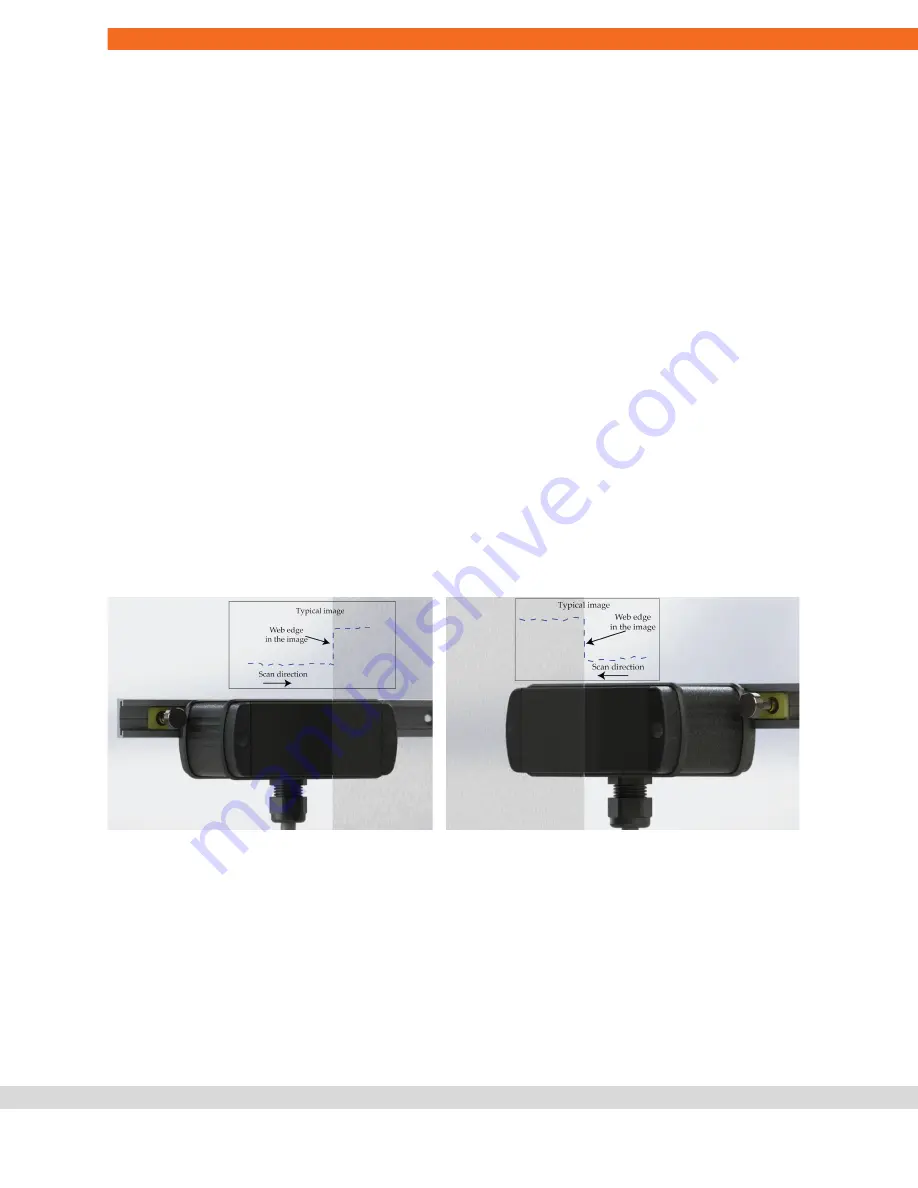
In edge sensing mode the sensor will look for the web edge scanning from the outside to the inside of the
sensor. For a left sensor the scan goes from left to right, while for a right sensor the scan goes from right to
left. A center sensor state is one in which both the edges of a web are within the field of view of the sensor.
Left sensor orientation (left) and right sensor orientation (right)
NOTE:
The sensor state is always defined based on relative position of the web with respect to the sensor.
For example, in the picture on the left above if the sensor is rotated upside down, which the cable gland on
the top, then the sensor orientation would change to right sensor.
WARNING:
If the sensor state is forced to Left, Right or Center, disconnection and reconnection of the
sensor will not automatically set the state as in the Auto mode. Everytime the sensor position is changed,
with respect to the web, the power user is responsible for ensuring the correct state of the sensor.
Content subject to change without notice
SCU5: Sensor and Web Guide Controller User Manual v 3.6| Page 39
Copyright © 2021 Roll-2-Roll Technologies LLC
+1-888-290-3215


