


Using the APP Recorder
6-18
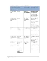
4.
From the
Channels
list, select one of the following choices:
All
Prints an oscillogram for each analog channel listed in the Point Assignment Record.
Selected
After you select this, click the
Select Channels
button to select the specific channels to print.
Group
Specific preset line groups can be printed.
5.
From the
Print Data Range
list, select the range of records to print:
All
Prints the entire length (X-axis) of all the oscillograms selected for printing.
Selected
Each data point in an oscillogram has a number. The starting number is “0” which is usually
the prefault portion of the waveform. The ending number depends on how long the fault or
recording lasted. To print a partial record, X- axis length, enter the data range.
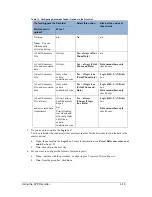
6.
In the
#Channels/Page box,
enter the number of oscillograms you want to appear on each page of
the printout.
Note:
Print fewer oscillograms on a page to increase the resolution on the Yscale.
7.
Limit to 100 Cycles per Page
check box causes the report to limit to 100 Cycles per page for
each channel displayed on a page.
8.
There are two types of triggers, analog triggers and event triggers. You can print these triggers in
conjunction with oscillograms. Triggers are represented by horizontal lines at the bottom of a
printed or displayed page. In the
Digital Channel Format
list, select how the trigger line should
appear, whether it is normal or abnormal:
Sequence Of Events /Triggers (Line on Abnormal)
This selection only prints the event channels or analog triggers that caused the system to
trigger and record. The state of other event channels is not printed. If a line is shown, it
represents the period of time the event was abnormal.
Sequence Of Events /Triggers (Line on Normal)
This selection only prints the event channels or analog triggers that caused the system to
trigger and record. The state of other event channels is not printed. If a line is shown, it
represents the period of time the event was normal.
All Events/Triggers (Line on Abnormal)
This selection prints the analog triggers and event channels that were in an abnormal state
when the record was created. If a line is shown, it represents the period of time the analog
trigger or event channel was abnormal.
All Events/Triggers (Line on Normal)
This selection prints the analog triggers and event channels that were in an abnormal state
when the record was created. If a line is shown, it represents the period of time the analog
trigger or event channel was normal.
9.
Spread digital among graphs
, if Spread digital check box is not checked, the Analog channels
are printed, then the Event Channels, on each page (See Figure 29). With Spread digital check box
checked the report shows the digital channels along with the Analog lines together (See Figure
30).
Содержание APP-601
Страница 1: ...APP 601 Recorder Operating Manual...
Страница 15: ...Introduction 1 1 1 Introduction...
Страница 18: ...2 1 2 Specifications...
Страница 25: ...Installation Overview 3 1 3 Installation Overview...
Страница 38: ...Hardware 4 1 4 Hardware...
Страница 61: ...Installing the Recorder Software 5 1 5 Installing the Recorder Software...
Страница 67: ...Using the APP Recorder 6 1 6 Using the APP Recorder...
Страница 117: ...Using the APP Recorder 6 51...
Страница 124: ...Using the APP Driver 7 1 7 Using the APP Driver...
Страница 128: ...Using the OScope 8 1 8 Using the OScope...
Страница 139: ...Other Information 9 1 9 Other Information...