


Hardware
4-18
4.5.7 Analog Circuit Board
An analog board contains 3 channels. The maximum number of analog channels in a Data chassis
is 30 (10 boards x 3 channels per board).
A channel can be setup as a voltage channel or current channel. To make this selection, software
settings must be made and two hardware jumpers per channel must be set. Software settings are
made in the Point Assignment Record and are discussed in a later section. The hardware setting is
made via two jumpers on each channel (JP1 & JP2 on the 1
st
board channel, JP3 & JP4 on the 2
nd
board channel, and JP5 & JP6 on the 3
rd
board channel). These are 3 pin headers.
To set up a channel for voltage input
, place the shorting jumper on the middle pin and the pin
towards the middle of the circuit board.
To set up a channel for current input
, place the shorting jumper on the middle pin and the pin
towards the 9 position black analog terminal block and blue rear panel.
*CAUTION*
Ensure that the voltage/current jumper is set properly before wiring to
the circuit board terminal block.
For a voltage channel, the input should be wired between V & C (voltage and common).
For a current channel, the input should be wired between I & C (current and common).
*WARNING*
The maximum input voltage for a voltage channel is 440VAC.
The maximum continuous current for a current channel is 15Amps.
The maximum current into a current channel for 0.5 seconds is
250Amps RMS or 140 Amps RMS for 2 Seconds
The maximum wire size for an analog terminal block is 12AWG
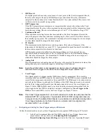
4.5.8
Front Panel LED’s
The Data Chassis uses front panel LED’s to give a quick indication of system status.
Green LED’s will illuminate when the recorder is operating properly. Red LED’s will illuminate if a
recorder problem exists. Yellow LED’s will illuminate when the system is recording data. An explanation
of each LED is listed in the following table.
Table 5: Description of LEDs
LED
Color
Description
POWER
Green
Illuminates when the system power is switched
on and is normal.
ON LINE
Green
Illuminates after the APP Recorder
Program/Service is running and normal system
operation has started.
1PPS
Green
Illuminates if the 1PPS signal is present from an
external satellite controlled clock. If no satellite
controlled clock is connected, this LED will
illuminate if the internally generated 1PPS signal
is present and normal.
OFF LINE
Red
Illuminates if the system is not ready to record.
V
Содержание APP-601
Страница 1: ...APP 601 Recorder Operating Manual...
Страница 15: ...Introduction 1 1 1 Introduction...
Страница 18: ...2 1 2 Specifications...
Страница 25: ...Installation Overview 3 1 3 Installation Overview...
Страница 38: ...Hardware 4 1 4 Hardware...
Страница 61: ...Installing the Recorder Software 5 1 5 Installing the Recorder Software...
Страница 67: ...Using the APP Recorder 6 1 6 Using the APP Recorder...
Страница 117: ...Using the APP Recorder 6 51...
Страница 124: ...Using the APP Driver 7 1 7 Using the APP Driver...
Страница 128: ...Using the OScope 8 1 8 Using the OScope...
Страница 139: ...Other Information 9 1 9 Other Information...