


Installation Overview
3-5
return and the customer provided that information to the factory, they will have jumpers between
the (-) event terminals.
*CAUTION*
APP Engineering manufactures an event circuit board that is
internally wetted and is setup for dry contact connection only. Do not
connect an external voltage to this internally wetted event circuit
board!
The board will have labeling indicating that it is for Dry Input. Again,
reference the print set for electrical drawings and important notes.
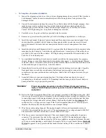
13.
Wire the recorder alarm outputs. The alarm outputs utilize a pluggable 16 position connector. The
maximum wire size for this connector is 14AWG. The alarm output contact is dry. The contacts
can break 0.5Amps @ 125VDC or 0.35A @ 250VDC.
14.
Connect your IRIG-B signal to the back of the DSP/IRIG circuit board. The IRIG-B connector is
labeled and is a standard BNC type connector. This board can accept a modulated or un-modulated
IRIG-B signal. However, a board jumper must be set to reflect the input type and software setting
in the Point Assignment Record must be made. Unless a satellite controlled clock was purchased
with the system, an IRIG-B coax cable is not provided.
15.
Connect the 1PPS signal from chassis to chassis. Connect the 1PPS out signal from the 1
st
Data
chassis to the 1PPS input of the 2
nd
Data chassis. Keep daisy chaining until the remaining data
chassis are connected. The 1PPS connector is a standard BNC connector. 1PPS interconnecting
cables have been provided with the system. The 1PPS signal can also be paralleled by using a
BNC “T” to reduce 1PPS latency.
16.
Ethernet cables have been provided with the system. Each chassis has one Ethernet RJ45
connector. On the Data chassis this connector is located on the DSP/IRIG circuit board. On the
Computer Control chassis it is simply located on the back panel and labeled DSP Enet. A cable
should be connected to each chassis and routed back to the system Ethernet switch. If a system
only consists of a Computer Control chassis and a single Data chassis, a switch is not required and
may not have been provided. Simply make a peer-to-peer connection between the two chassis.
17.
Connect power cables to the Ethernet switch. A power cable has been provided. It should be
connected from the Data Chassis power supply circuit board (terminals 3&4) to the input terminal
block of the Ethernet switch. The voltage is 12Vdc.
*CAUTION*
It is possible that a specially requested Ethernet switch was used and
it may connect directly to 125VDC.
Reference the print set for electrical drawings and important notes.
18.
Main input power to the system connects to the 1
st
Data chassis. Input voltage can be 88-264Vac
or 86-373 Vdc or 125Vdc. Other voltage input options are available. All chassis have power
connected to terminals 1 & 2 of the power circuit board. It is likely that wires have been provided
for paralleling power from Data chassis to Main Data Chassis (usually the 1
st
Data Chassis).
Power to the Computer Control chassis should come from the Data chassis. Terminals 5 & 6 on
the Data chassis power supply circuit board should be used to power the Computer Control
chassis. It is likely wires have been provided for connecting output power from the Main Data
chassis to the power input of the Computer Control chassis.
*WARNING*
All #6 ring terminals connecting to the power circuit board should be
insulated ring terminals.
19.
Ensure that all chassis power switches are in the OFF position.
Содержание APP-601
Страница 1: ...APP 601 Recorder Operating Manual...
Страница 15: ...Introduction 1 1 1 Introduction...
Страница 18: ...2 1 2 Specifications...
Страница 25: ...Installation Overview 3 1 3 Installation Overview...
Страница 38: ...Hardware 4 1 4 Hardware...
Страница 61: ...Installing the Recorder Software 5 1 5 Installing the Recorder Software...
Страница 67: ...Using the APP Recorder 6 1 6 Using the APP Recorder...
Страница 117: ...Using the APP Recorder 6 51...
Страница 124: ...Using the APP Driver 7 1 7 Using the APP Driver...
Страница 128: ...Using the OScope 8 1 8 Using the OScope...
Страница 139: ...Other Information 9 1 9 Other Information...