


Hardware
4-16
4.5.6 DSP/IRIG Circuit Board
The DSP/IRIG board is the heart of a Data chassis. The DSP IC contains the recorder driver program and is
responsible for collecting data from the analog and event inputs. The DSP IC performs mathematical
calculations on the data received from each analog and event channel and decides if a trigger condition
exists. Prefault data is stored in a circular buffer. If a trigger condition does not exist, the oldest prefault
data is overwritten by new incoming prefault data (FIFO). If a trigger condition is measured, the prefault
data plus incoming data is routed to the Computer Control chassis via the Ethernet connection. If
continuous recording is enabled, the above triggering process is carried out and incoming data from the
analog channels are continuously routed to the Computer Control chassis (all with data sample time
stamping.)
The DSP/IRIG board can accept a modulated or un-modulated IRIG-B input signal from a satellite-
controlled clock. The top BNC connector, J6, is the IRIG-B input. Each data sample is time stamped to the
microsecond. Data is aligned with the 1PPS rising edge and the accuracy of the time stamp is no better than
the accuracy of the 1PPS signal coming from the satellite controlled clock.
Table 4: SyncMethod and Corresponding Hardware 3-PIN Jumper Position
SyncMethod
JP2 3-PIN Jumper (DSP/IRIG Circuit Board)
Un-modulated IRIG-B
Short middle pin & pin close to panel
Modulated IRIG-B
Short middle pin & pin away from panel
Note:
T
here are “un-mod” and “mod” labels on back of DSP board under the JP2.
If the DSP/IRIG board loses the 1PPS signal from the satellite-controlled clock, the DSP IC no longer
receives a 1PPS interrupt signal. In this case, the DSP will rely on its own 1PPS signal that is generated
from an onboard 25MHz crystal. The crystal has an accuracy of 100ppm which translates to an error of
0.1msec/1sec (8.6sec/day).
The system computer, located in the Computer Control chassis, is time synchronized with the satellite-
controlled clock. If the recorder is powered up and the there is no satellite controlled clock present, the
beginning time of day is obtained from the computer.
Note:
The recorder will not synchronize if the computer time and the external satellite controlled
clock are more than 2 hours apart. Ensure the Computer and satellite clock are set for
the same time zone and daylight savings time is turned off on the computer.
*CAUTION*
We recommend turning on the satellite controlled clocks extended
IEEE C37.118 IRIGB format. If the clock does not have this feature, we
recommend not turning off the computer’s Daylight Saving Time.
If the recorder contains multiple Data chassis, the 1PPS signal is routed from the first Data chassis down to
the next Data chassis via the 1PPS out/in connectors.
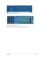
The DSP/IRIG circuit board is always located in the 7
th
board slot, from the left side of the
chassis. There is one DSP/IRIG circuit board per Data chassis.
Major hardware/firmware items on this board include the following:
High Performance Digital Signal Processing IC (100MHz, 32bit, 1MB On Chip Dual-Ported
SRAM, Integrated I/O Processor With Multiprocessing Support and Multiple Internal Buses
To Prevent I/O Bottlenecks, 15x15 BGA style package)
256MB High Speed SDRAM IC
Содержание APP-601
Страница 1: ...APP 601 Recorder Operating Manual...
Страница 15: ...Introduction 1 1 1 Introduction...
Страница 18: ...2 1 2 Specifications...
Страница 25: ...Installation Overview 3 1 3 Installation Overview...
Страница 38: ...Hardware 4 1 4 Hardware...
Страница 61: ...Installing the Recorder Software 5 1 5 Installing the Recorder Software...
Страница 67: ...Using the APP Recorder 6 1 6 Using the APP Recorder...
Страница 117: ...Using the APP Recorder 6 51...
Страница 124: ...Using the APP Driver 7 1 7 Using the APP Driver...
Страница 128: ...Using the OScope 8 1 8 Using the OScope...
Страница 139: ...Other Information 9 1 9 Other Information...