


Hardware
4-2
4.1 Available Computer Control Chassis
The APP-601 recorder can be purchased with either of the following Computer Control chassis:
1) APP-601 Computer Control Chassis (fanless)
2) APP-501 Computer Control Chassis (with fan & human interface)
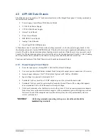
4.2 Major Duties of the Computer Control Chassis
The major duties of the Computer Control chassis are:
Communicate with each DSP circuit board carrying out functions such as; collecting data,
downloading settings, and downloading new software.
Receive, organize and store raw data.
Convert raw data into COMTRADE C37.111-2013 format.
Calculate continuous frequency, RMS, and phase data.
Communicate with the APP ClearView master station software via modem, network, or directory.
Output data in DNP-3 format via RS232 or Ethernet to a remote terminal unit or similar.
Output PMU data.
Provide a means for a local user to look at settings, change settings, view real-time oscillograms,
look at stored records, communicate with someone at a master station, or even call another
recorder and download records for review and analysis.
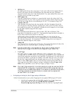
4.3 APP-601 Computer Control Chassis
The APP-601 Computer Control chassis is constructed in a 3U 19” rack mount chassis. The chassis depth is
approximately 9.8”. Housed inside the chassis are an industrial single board fanless computer, modem,
Compact Flash, 2.5” Hard Drive, 12V 100Watt power supply, 12V 50Watt power supply, and rear slide in
power supply circuit board.
The single board computer (with compact flash and 2.5” hard drive), USB modem, and a connector circuit
board are all mounted on a slide out shelf. The chassis rear panel is attached to the shelf and can slide out of
the chassis by loosening the rear panel thumb screws and carefully pulling on the rear panel.
The computer chassis can be powered from a 86-373Vdc or 88-264Vac source. Ideally it should be
powered from a Data chassis via its power supply terminal block (terminals 5 & 6). In this manner, the
Data chassis can control power to the Computer Control chassis. This gives a remote user, local user, or the
system watchdog a means of rebooting the computer chassis.
The 12V power supplies are mounted to the chassis front panel. This allows for maintenance access and
heat sinking.
*WARNING*
Always turn OFF chassis power before opening the chassis front
panel. The input sides of the power supplies have 125V or 250V wired
to them. This voltage can be deadly! Only trained experienced
electrical personnel should open the chassis front panel and only with
the power OFF.
The rear slide in power supply circuit board contains a 2A fuse, components for surge protection, a power
switch, and a 6 position terminal block. Power is connected to terminals 1 & 2 and passes thru the board via
connector X3 to the 12V power supplies discussed above. 12V from the 50W supply returns to the power
supply circuit board via connector X2 and lands on terminals 3 and 4 of the terminal block. This 12V
Содержание APP-601
Страница 1: ...APP 601 Recorder Operating Manual...
Страница 15: ...Introduction 1 1 1 Introduction...
Страница 18: ...2 1 2 Specifications...
Страница 25: ...Installation Overview 3 1 3 Installation Overview...
Страница 38: ...Hardware 4 1 4 Hardware...
Страница 61: ...Installing the Recorder Software 5 1 5 Installing the Recorder Software...
Страница 67: ...Using the APP Recorder 6 1 6 Using the APP Recorder...
Страница 117: ...Using the APP Recorder 6 51...
Страница 124: ...Using the APP Driver 7 1 7 Using the APP Driver...
Страница 128: ...Using the OScope 8 1 8 Using the OScope...
Страница 139: ...Other Information 9 1 9 Other Information...