


124
128KB Memory Upgrade
Black/White LCD Mini-Touch Panels
5.
Carefully pry the 32KB IC out of the 32-socket connector labeled U4 with a non-
conducting flat-blade tool and insert the 128K IC.
6.
Rotate the circuit card back to the original position and place it in the mini-
touch panel housing.
7.
Place the bottom panel onto the mini-touch panel and align the screw holes.
Insert the four Phillips-head screws and tighten.
8.
Plug all connectors back into the mini-touch panel.
AXU-MLC (/PB) and AXM-MLC (/PB)
Install the 128KB IC into the AXU-MLC (/PB) and AXM-MLC (/PB) mini-touch
panels:
1.
Discharge the static electricity from your body by touching a grounded object.
2.
Insert a flat-blade tool into the release slot on the mini-touch panel’s bezel and
remove the engraved overlay.
3.
Remove the four #6-32 mounting screws and carefully lean the mini-touch panel
backward to expose the AXlink and RS-232 (optional) wiring.
4.
Disconnect the AXlink and RS-232 4-pin header and remove the mini-touch
panel from the back box or equipment rack.
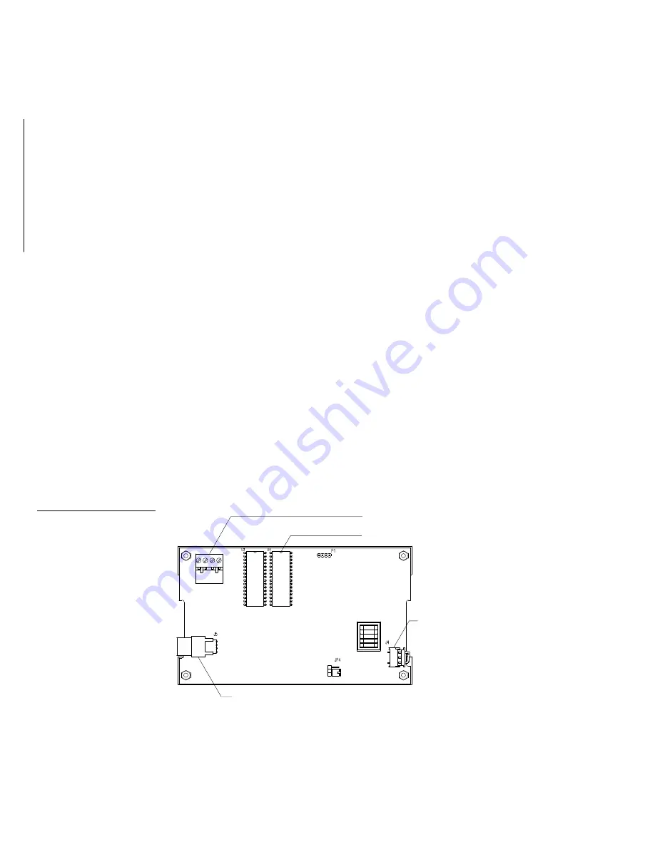
5.
Flip the mini-touch panel facedown onto a soft cloth. Figure 174 shows the
connectors on the circuit card.
Backlight
connector
4-pin AXlink connector
Connector side of circuit card
32-socket IC connector (U4)
Touch overlay
ribbon cable
Figure 174
Mini-touch panel circuit card,
and 32-socket IC connector
(U4)
Содержание AXM-MLC
Страница 8: ...vi Table of Contents Black White LCD Mini Touch Panels ...
Страница 36: ...28 Mini Touch Panel Basics Black White LCD Mini Touch Panels ...
Страница 114: ...106 Mini Touch Panel Program Reference Black White LCD Mini Touch Panels ...
Страница 130: ...122 Replacing the Lithium Batteries Black White LCD Mini Touch Panels ...
Страница 140: ...132 Technical Support Black White LCD Mini Touch Panels ...


