background image

Black/White LCD Mini-Touch Panels

Mini-Touch Panel Program Reference

103

Use the send option to  send a printable image of buttons and pages to a PC over the
AXlink or RS-232 4-pin headed in the mini-touch panel. The PC must be  running the
TPDOC or TPDesign software  program before you send the print file. Refer to the
TPDOC or TPDesign instruction manuals for more information.

• 

YES

     Receives the PC file via the AXlink connector on the mini-touch panel

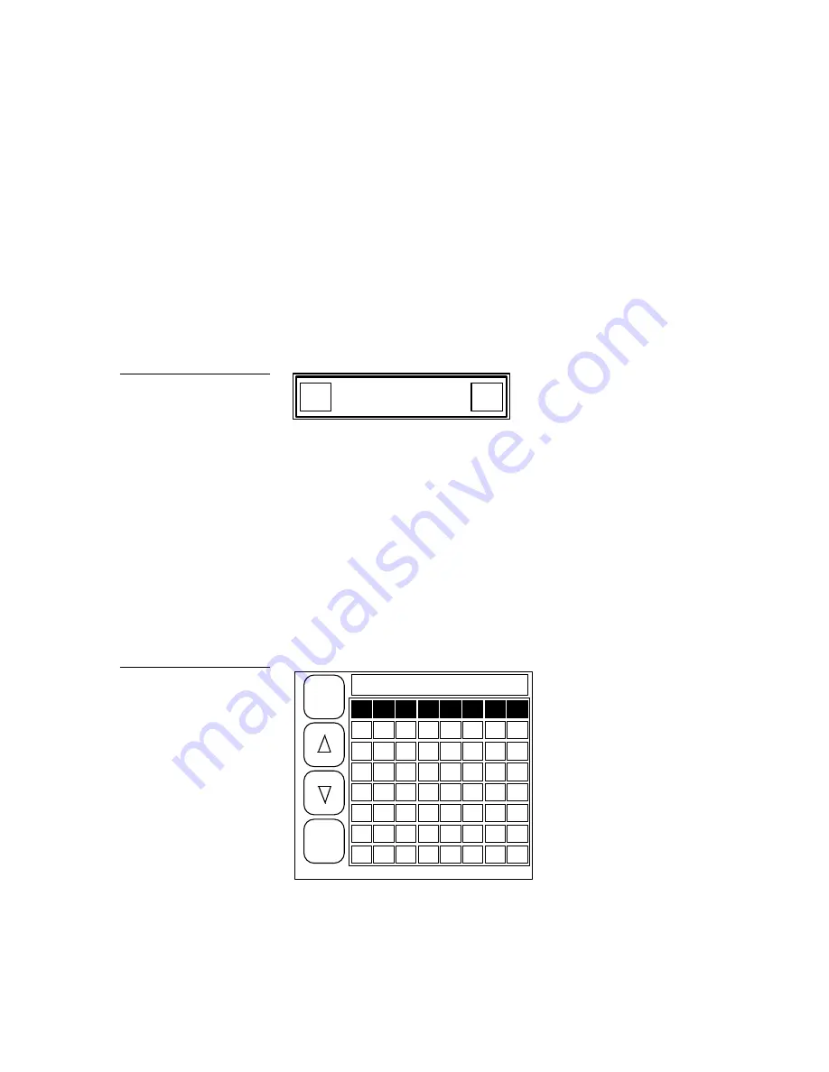
and opens the decision box in  Figure 162.

• 

NO

     Receives the PC file via the RS-232 4-pin header in the mini-touch panel

and opens the decision box in  Figure 162.

YES

NO

PRESS YES TO START.

PRESS NO TO QUIT.

• 

YES

     Sends the print file to the PC. The mini-touch panel returns to the

startup page when the file transfer is complete.

• 

NO

     Cancels the file transfer and returns to the current page.

Function map

Choose the FUNCTION MAP option to open the channel code map page shown in
Figure 163

9

10

11

12

13

14

15

16

17

18

19

20

21

22

23

24

25

26

27

28

29

30

31

32

33

34

35

36

37

38

39

40

41

42

43

44

45

46

47

48

49

50

51

52

53

54

55

56

57

58

59

60

61

62

63

64

RETURN

OTHER

MAP

CHANNEL CODE MAP:

touch number to test code

1

2

3

4

5

6

7

8

Figure 162

Start or quit decision box

Figure 163

Channel code map page

Содержание AXM-MLC

Страница 1: ... ODFN2 KLWH 0LQL07RXFK 3DQHOV LUPZDUH YHUVLRQ 5 RU ORZHU QVWUXFWLRQ 0DQXDO 818 0LQL07RXFK 3DQHOV DQG FFHVVRULHV ...

Страница 2: ...ty or made by you for a third party This limitation of liability applies whether damages are sought or a claim is made under this warranty or as a tort claim including negligence and strict product liability a contract claim or any other claim This limitation of liability cannot be waived or amended by any person This limitation of liability will be effective even if AMX or an authorized represent...

Страница 3: ...d 9 AXM MLC rack mount 11 AXW MLC PB wood enclosure 12 Wiring the Mini Touch Panels 13 Guidelines 14 Preparing captive wires 15 Using the AXlink mini XLR connector for data and power TiltScreen and wood enclosure 15 Using the AXlink mini XLR connector and external 12 VDC power supply TiltScreen and wood enclosure 15 Using the AXlink 4 pin connector UniMount and rack mount 16 Using the AXlink 4 pin...

Страница 4: ... Touch Panel Page 29 Overview 29 Activate the Editor Bar 29 Create a Page 31 Add a page 31 Go to NEW PAGE 33 Create a Button 34 Add a button 34 Resize the button 35 Button Attributes 36 Set the button attributes 36 Set the border 37 Set the channel code 38 Set the page flip 38 Add Text 39 Add text to a button 39 Create a Joy stick 40 Add a joy stick on a page 40 Set the joy stick attributes 41 Set...

Страница 5: ... WAVE 53 Set time and date 55 Double beep 56 Protected setup 56 Set background 57 Bright contrast 58 Protected Setup Page 59 Open the Protected Setup Page 59 Protected Setup Page Buttons 60 Editor 60 Setup password 61 Auto assign 61 Set serial 62 Set device 64 Page password 65 Power up page 65 Calibrate 66 Page tracking 66 LCD timer message 66 Editor Bar 69 Button Menu Options 70 Add 71 Move 71 Co...

Страница 6: ...char term 88 32 char term 88 Vertical graph 88 Icon feedback 91 Joy stick 94 Drawings 96 Bright contrast 97 System Menu Options 98 Clear buttons 98 Clear drawings 99 Memory 100 Send file 100 Receive file 101 Move edit bar 102 Print 102 Function map 103 Function show 105 AXCESS Programming 107 Overview 107 System Send_Commands 107 Variable Text Send_Commands 113 WavePack Button Attribute String_Com...

Страница 7: ...T MLC PB 117 AXU MLC PB and AXM MLC PB 119 AXW MLC PB 120 128 KB Memory Upgrade 123 Operation 123 AXT MLC PB 123 AXU MLC PB and AXM MLC PB 124 AXW MLC PB 125 Specifications 127 Overview 127 AXT MLC PB 127 AXU MLC PB 128 AXM MLC PB 129 AXW MLC PB 130 Technical Support 131 Overview 131 Index 133 Overview 133 ...

Страница 8: ...vi Table of Contents Black White LCD Mini Touch Panels ...

Страница 9: ...logos and drawings You can also use the TPDOC or TPDesign custom touch panel design programs AMX offers to enhance your mini touch panel designs Figure 1 shows an AXT MLC TiltScreen mini touch panel Figure 2 lists the mini touch panel types and product names described in this manual Black white LCD mini touch panel types and product names Product names Panel types Standard Pushbuttons TiltScreen A...

Страница 10: ... wireless power pack AXCESS program control for 1 way wireless communication between any AMX RF and high low frequency IR device and the AXT MLC mini touch panel equipped with a SMT PKM Mini SmartPack wireless power pack Features The mini touch panel offers the following features 2 9 inch x 3 9 inch HW LCD 320 x 240 HV pixel black white LCD Up to 12 external pushbuttons 6 on either side of display...

Страница 11: ...ouch panels use a 4 pin male mini XLR connector for power and data and the AXU MLC PB and AXM MLC PB mini touch panels use a 4 pin AXlink connector for power and data The mini touch panels connect to an AXCESS Control System AXCENT 2 Integrated AXCESS Control System or the AXB EM232 Enhanced Master RS 232 Controller You can also connect an optional Microsoft or Logitech serial mouse to the RS 232 ...

Страница 12: ...Touch Panel Basics Basic elements associated with the mini touch panel operating system such as button types message and editor selection bars and keyboards Designing a Mini Touch Panel Page Step by step instructions to create a mini touch panel page button joy stick and bargraph Mini Touch Panel Program Reference Describes all the mini touch panel operations AXCESS Programming Lists AXCESS system...

Страница 13: ...ouch panels Mounting the Mini Touch Panels The following describes how to mount the UniMount and rack mount mini touch panels The TiltScreen mini touch panel can be mounted on any flat surface AXU MLC PB and low profile back box Mount the AXU MLC PB and low profile back box Figure 4 Low profile back box AXU MLC bezel Release slot Engraved overlay Figure 4 AXU MLC and low profile back box ...

Страница 14: ... MLC PB s bezel and remove the engraved overlay 3 Place the AXU MLC PB into the cutout and mark the screw insert positions as shown in Figure 4 4 Remove the AXU MLC PB and drill four 6 32 insert holes Then place a threaded insert into each hole 5 Attach the data and power wiring to the AXU MLC PB Refer to Wiring the Mini Touch Panels for wiring diagrams and pinout descriptions Figure 5 AXU MLC and...

Страница 15: ...y power AXU MLC PB and BB MTP solid surfaces Mount the AXU MLC PB and BB MTP Figure 6 into a solid surface Release slot Solid surface mounting flanges Knockout BB MTP UniMount enclosure AXU MLC bezel Engraved overlay Stud mounting holes 1 Cut the solid surface according to the cutout dimensions shown in Figure 7 2 Insert a flat head screwdriver into the release slot on the AXU MLC PB s bezel and r...

Страница 16: ...x Remove the back box and discard 4 Place the BB MTP into the cutout and mark the threaded insert positions as shown in Figure 7 5 Remove the BB MTP and drill eight holes as shown in Figure 6 Then place 6 32 threaded inserts into the four holes marked B in the cutout dimensions illustration 6 Disconnect the AXlink connector from the AMX control system that supplies power and data to the AXU MLC PB...

Страница 17: ...rovided with the enclosure 12 Insert the engraved overlay back into the bezel 13 Connect the AXlink wiring to the AMX control system and RS 232 wiring to the external RS 232 device The AXU MLC PB will beep when you apply power AXU MLC PB and BB MTP plasterboard Mount the AXU MLC PB and BB MTP Figure 8 into a plasterboard surface or equivalent Release slot Plasterboard surface mounting flanges Knoc...

Страница 18: ...driver into the release slot on the AXU MLC PB s bezel and remove the engraved overlay 3 Lay the AXU MLC PB facedown onto a soft cloth and remove the four screws from the low profile back box Remove the back box and discard 4 Place the BB MTP into the cutout and mark the threaded insert positions as shown in Figure 9 Figure 9 AXU MLC PB and BB MTP cutout dimensions ...

Страница 19: ...or complete wiring information 10 Fasten the AXU MLC PB to the BB MTP with the 6 32 screws supplied with the enclosure 11 Insert the engraved overlay back into the bezel 12 Connect the AXlink wiring to the AMX control system and RS 232 wiring to the external RS 232 device The AXU MLC PB will beep when you apply power AXM MLC rack mount Mount the AXM MLC Figure 10 rack mount into an electronic equi...

Страница 20: ...AXlink wiring to the AMX control system and RS 232 wiring to the external RS 232 device The AXM MLC will beep when you apply power AXW MLC PB wood enclosure Install the AXW MLC PB Figure 11 wood enclosure 1 Thread the incoming AXlink cable to the AXW MLC PB 2 Disconnect the AXlink connector from the AMX control system that supplies power and data to the AXW MLC PB 3 Connect the mini XLR connector ...

Страница 21: ...er and data Figure 12 shows the rear panel AXlink connector on the TiltScreen mini touch panel Figure 13 shows the rear panel AXlink connector on the rack mount mini touch panel Figure shows the AXlink and RS 232 connectors on the AXW MLC PB mini touch panel s circuit card Rear view Mini XLR 4 pin male AXlink and power connector Top view 4 pin male AXlink connector Figure 12 TiltScreen mini touch ...

Страница 22: ...ngths for using AXlink power are based on a minimum of 13 5 volts available at the control system s power supply Wiring guidelines Wire size Maximum wiring length 18 AWG 234 feet 20 AWG 148 feet 22 AWG 92 feet 24 AWG 58 feet If you install the mini touch panel farther away from the control system than recommended in Figure 15 connect a 12 VDC power supply to the TiltScreen UniMount and rack mount ...

Страница 23: ...een and wood enclosure Connect the control system s AXlink connector to the mini XLR connector male on the rear panel of the TiltScreen and wood enclosure mini touch panels for data and 12 VDC power as shown in Figure 16 GND BLK 2 1 PWR RED AXM GRN AXP WHT 3 4 1 2 3 4 1 GND BLK 3 AXP WHT 2 AXM GRN 4 PWR RED Control system 4 pin mini XLR connector Using the AXlink mini XLR connector and external 12...

Страница 24: ... in Figure 18 UniMount or rack mount AXlink connector Control system 1 3 2 4 GND BLK AXP WHT AXM GRN PWR RED GND BLK AXP WHT AXM GRN PWR RED 1 3 2 4 Using the AXlink 4 pin connector and external 12 VDC power supply Connect the control system s AXlink connector to the AXlink connector on the rear panel of the mini touch panel as shown in Figure 19 Figure 17 Mini XLR connector to external 12 VDC pow...

Страница 25: ...onnector s PWR terminal Using the RS 232 4 pin header for mouse control or data wood enclosure The dual function RS 232 4 pin header In the UniMount rack mount and wood enclosure s support most standard serial mouse control devices and RS 232 communication protocols for PC data transmission Refer to Figure 20 for RS 232 4 pin header specifications and Figure 21 for the wiring diagram RS 232 4 pin ...

Страница 26: ...an the touch overlay 1 Disconnect the AXlink RS 232 and mini XLR connector from the mini touch panel 2 Using a cotton cloth spray a small amount of cleaning solution consisting of 50 percent isopropyl alcohol and 50 percent water onto the cloth 3 Clean the touch overlay with the damp cloth Then wipe the touch overlay with a dry cloth 4 Reconnect the AXlink RS 232 and mini XLR connector to the mini...

Страница 27: ...wings to a mini touch panel page and then designate the control functions for each object The number of objects depends on the type and quantity of external devices you want to control with the mini touch panel and AXCESS Control System When you create multiple pages you must link them with buttons Figure 23 shows how to link five mini touch panel pages to the Main page Note that each page contain...

Страница 28: ...uch the button General Buttons General buttons are part of the mini touch panel software program and cannot be changed You use general buttons to specify panel communication parameters and create or revise pages Some button examples include the message bar editor bar selection adjustment keypad page menu decision status and keyboard Message bar The message bar Figure 24 appears when you press the ...

Страница 29: ...2 CHAR TERM VERTICAL GRAPH ICON FEEDBACK JOYSTICK DRAWINGS BRIGHT CONTR BUTTON PAGE ICONS SYSTEM EXIT Editor bar Selection button Selection buttons Figure 26 appear throughout the mini touch panel software program to open pages activate YES NO prompt messages or set communication parameters PROTECTED SETUP Information button Information buttons contain serial numbers and firmware version informati...

Страница 30: ...touch panel BAUD 19 2 UP DN Button title Variable data Keypad buttons The keypad button opens a keypad Figure 29 so you can enter a password or value assignment All keypad buttons are active except for the entry display 0 SET TIME SET 1 2 3 4 5 0 6 0 7 8 9 Entry display Keypad entry 0 9 CLEAR Resets entry to 0 ENTER Processes entry if correct CLEAR ENTER Figure 27 Information button example Figure...

Страница 31: ...ctive Use the up and down arrows to scroll through the list of page names The highlight bar marks the page name as you scroll through the list Press the ENTER button to designate the Go To page or Startup page Decision buttons Decision buttons Figure 31 appear when an operation has two options YES NO Decision Text Goes Here Decision buttons appear when y ou exit the editor bar send or receive a dr...

Страница 32: ...NL CHARS ENTER DEL MORE KEYS FONT ABORT EXIT SAVE Y U I O P H J K L N M CAP LOCK BACK SPACE SHIFT SPACE ALT INTNL CHARS ENTER DEL MORE KEYS FONT ABORT EXIT SAVE B Page 1 Page 2 Press the MORE KEYS button to toggle between keyboard pages 1 and 2 You use the keyboard pages during initial setup if you change the time out message or power up message The keyboard pages also appear when you add new page...

Страница 33: ...CK on INTNL CHARS Changes the keyboard to two additional pages of international characters for the character set font in use SPACE Inserts a space character in your line of text SHIFT Shifts text characters between upper case and lowercase ALT Changes the keyboard to alternate keyboard pages 1 and 2 that contain additional numbers and punctuation characters Direction arrows Moves the cursor left r...

Страница 34: ...Panels Aa Aa Aa AaBb AaBbCc Aa Aa Aa Aa Aa FIXED SYMBOLS VARI ABLE SYMBOLS FIXED SYMBOLS Opens the Fixed Symbol pages that contain 22 control symbols Figure 35 shows the first page of fixed symbols Figure 34 Font page example Figure 35 Fixed Symbol page 1 ...

Страница 35: ...ure 36 is a variable symbol page example Refer to the TPDOC or TPDesign instruction manuals to download symbols into mini touch panel memory ABORT Closes the keyboard page without making any text or graphic character changes EXIT SAVE Closes the keyboard page and stores the text or graphic changes to memory Figure 36 Variable Symbols page example ...

Страница 36: ...28 Mini Touch Panel Basics Black White LCD Mini Touch Panels ...

Страница 37: ...out all the operations you can use to design mini touch panel pages Activate the Editor Bar Before you can design a mini touch panel page you need to activate the editor bar When you power up the panel the first page you should see is the Main page Figure 37 If you have a pre programmed panel you may not see the Main page Refer to the Editor bar and Go to information in the Mini Touch Panel Progra...

Страница 38: ... 15 UP DN AXlink vX XXV SERIAL NO 923 00 0001 SmartPack WAVE AXlink SET TIME AND DATE DOUBLE BEEP 1 2 3 4 5 0 6 1988 7 8 9 CLEAR ENTER 3 Type 1988 and press ENTER to open the Protected Setup page Figure 40 If you enter a wrong number press CLEAR and re enter the number Refer to the Set Password subsection to change a password Figure 38 Setup page Note The SmartPack button appears in the Setup page...

Страница 39: ...igure 40 and EXIT to close the Protected Setup page and return to the Main page The editor bar appears at the top of the Main page Figure 41 BUTTON PAGE ICONS SYSTEM EXIT SETUP MAIN PAGE Editor Bar Create a Page You create mini touch panel pages using the Page menu option in the editor bar Add a page 1 Press PAGE on the editor bar to open the menu options shown in Figure 42 Figure 40 Protected Set...

Страница 40: ...E THE NEW PAGE A UNIQUE NAME UP TO 20 LETTERS TOUCH SCREEN TO CONTINUE Q W E R T A S D F G Z X C V CAP LOCK BACK SPACE SHIFT SPACE ALT INTNL CHARS ENTER DEL MORE KEYS FONT ABORT EXIT SAVE 3 Type New Page Figure 44 using keyboard pages 1 and 2 Press the MORE KEYS button to toggle between the keyboard pages The page name can be up to 20 letters Figure 42 Page menu options Note The message bar shows ...

Страница 41: ...TER DEL MORE KEYS FONT ABORT EXIT SAVE B Page 1 Page 2 4 Press EXIT SAVE to add NEW PAGE to panel memory close the keyboard and return to the Main page Go to NEW PAGE 1 Press PAGE on the editor bar to open the page menu options shown in Figure 45 PAGE MAIN PAGE EXIT SETUP MAIN PAGE ADD COPY RENAME DELETE GO TO PASSWD PG FLIP PRINT 2 Press the GO TO option to open the page list shown in Figure 46 F...

Страница 42: ...visible before you create a button If not start at the beginning of this section Add a button 1 Press BUTTON on the editor bar to open the button menu options shown in Figure 47 PAGE NEW PAGE EXIT ADD MOVE COPY IMAGE DELETE RESIZE EDIT TEXT ATTRIBUTES SAVE PASTE 2 Press ADD to add a button to NEW PAGE The message bar shown in Figure 48 instructs you how to add a button The first touch point is the...

Страница 43: ...point Width Height 4 Press EXIT in the editor bar to exit add mode Resize the button 1 Press BUTTON on the editor bar again to open the menu options shown in Figure 50 PAGE NEW PAGE EXIT ADD MOVE COPY IMAGE DELETE RESIZE EDIT TEXT ATTRIBUTES SAVE PASTE Button 2 Press the RESIZE option to resize the button when the message bar appears Figure 48 Add a button message bar Figure 49 Add a button exampl...

Страница 44: ...ton Attributes You can use the ATTRIBUTES option on the editor bar to set button borders page flips and assign channel and level codes Set the button attributes 1 Press BUTTON on the editor bar to open the button menu options shown in Figure 52 PAGE NEW PAGE EXIT ADD MOVE COPY IMAGE DELETE RESIZE EDIT TEXT ATTRIBUTES SAVE PASTE Button 2 Press ATTRIBUTES and the button you added to open the Attribu...

Страница 45: ...ONT Set the border 1 Press BORDER to open the Border options page Figure 54 SINGLE WIDE DOUBLE WIDE NO BORDER SINGLE DIAMOND TRIPLE WIDE SINGLE RAISED DOUBLE RAISED SINGLE ROUNDED DOUBLE ROUNDED TRIPLE RAISED DOUBLE 3 SINGLE SHADOW NO BORDER SPECIAL DOUBLE 2 SINGLE DOUBLE DIAMOND 2 Press SHADOW to reset the button border to shadow style Figure 53 Attributes page Figure 54 Border options page ...

Страница 46: ...keypad and return to the Attributes page Set the page flip 1 Press PAGE in the Attributes page to open the page list Figure 55 NEW PAGE NONE ENTER PREVIOUS MAIN PAGE 2 Press the up or down arrow to move the highlight bar to MAIN PAGE 3 Press ENTER to set the page flip to the MAIN PAGE 4 Press EXIT in the Attributes page to store the new button attributes in memory and return to the current page 5 ...

Страница 47: ...E Button 2 Press EDIT TEXT to add text in the button when the message bar appears 3 Touch the button to open the keyboard pages 1 or 2 shown in Figure 57 Press the MORE KEYS button to toggle between the keyboard pages NEW PAGE Q W E R T A S D F G Z X C V CAP LOCK BACK SPACE SHIFT SPACE ALT INTNL CHARS ENTER DEL MORE KEYS FONT ABORT EXIT SAVE NEW PAGE Y U I O P H J K L N M CAP LOCK BACK SPACE SHIFT...

Страница 48: ...ar to exit edit text mode Create a Joy stick You can create a joy stick Figure 58 with the ICONS option in the editor bar Joy sticks are vertical and horizontal direction controllers you can use for camera operations such as pan and tilt Before you start make sure to connect the panel to your AXCESS Control System Otherwise the joy stick may not work properly Refer to Mini Touch Panel Program Refe...

Страница 49: ...Touch point Set the joy stick attributes 1 Press BUTTON on the editor bar to open the button menu options shown in Figure 61 PAGE NEW PAGE EXIT ADD MOVE COPY IMAGE DELETE RESIZE EDIT TEXT ATTRIBUTES SAVE PASTE Joystick MAIN PAGE 2 Press ATTRIBUTES to set the joy stick attributes when the message bar appears 3 Touch the joy stick to open the Joy stick Attributes page shown in Figure 62 Figure 60 Ad...

Страница 50: ... 6 in the keyboard The AXCESS software program uses level codes 1 through 7 to identify the joy stick and its associated operations Refer to Mini Touch Panel Program Reference for more information 3 Press ENTER to store the level code in memory 4 Press EXIT in the Attributes page to store the new joy stick attributes in memory and return to the current page 5 Press EXIT in the editor bar to exit t...

Страница 51: ...line levels or light levels Before you start make sure to connect the panel to your AXCESS Control System Otherwise the bargraph may not work properly Refer to the Mini Touch Panel Program Reference for more information Add a bargraph to a page 1 Press ICONS on the editor bar to open the icons menu options shown in Figure 65 TIME DATE E TIMER 16 CHAR TERM 32 CHAR TERM VERTICAL GRAPH ICON FEEDBACK ...

Страница 52: ...6 shows the method to add a bargraph Touch point Set the bargraph attributes 1 Press BUTTON on the editor bar to open the button menu options shown in Figure 67 PAGE NEW PAGE EXIT ADD MOVE COPY IMAGE DELETE RESIZE EDIT TEXT ATTRIBUTES SAVE PASTE Bar graph MAIN PAGE 2 Press ATTRIBUTES to set the bargraph attributes when the message bar appears Figure 66 Add and move a bargraph example Figure 67 But...

Страница 53: ...hrough 8 to identify the bargraph and its associated operations Refer to Mini Touch Panel Program Reference for more information 3 Press ENTER to store the level code in memory 4 Press EXIT in the Attributes page to store the new bargraph attributes in memory and return to the current page 5 Press EXIT in the editor bar to exit the attribute s mode Link the New Page to the Main Page You use the At...

Страница 54: ...s the MORE KEYS button to toggle between the keyboard pages 5 Press DEL four times to delete MAIN 6 Type NEW The revised text appears in the keyboard window as shown in Figure 70 NEW PAGE Q W E R T A S D F G Z X C V CAP LOCK BACK SPACE SHIFT SPACE ALT INTNL CHARS ENTER DEL MORE KEYS FONT ABORT EXIT SAVE NEW PAGE Y U I O P H J K L N M CAP LOCK BACK SPACE SHIFT SPACE ALT INTNL CHARS ENTER DEL MORE K...

Страница 55: ...shown in Figure 71 SETUP MAIN PAGE PAGE NEW PAGE EXIT ADD MOVE COPY IMAGE DELETE RESIZE EDIT TEXT ATTRIBUTES SAVE PASTE 10 Press ATTRIBUTES and the NEW PAGE button to open the Attributes page shown in Figure 72 BORDER VARIABLE TEXT NONE PAGE NONE STRING NONE FEEDBACK CHANNEL CHANNEL CODE NONE EXIT EXIT NO CHANGE BRING BUTTON TO FRONT Figure 71 Button menu options Figure 72 Attributes page ...

Страница 56: ...age to store the new button attributes in memory and return to the current page 15 Press EXIT in the editor bar to exit the attribute s mode 16 Touch the NEW PAGE and MAIN PAGE buttons to flip between pages Close the Editor Bar After you finish designing the mini touch panel page close the editor bar Exit editor mode 1 Touch EXIT on the editor bar Figure 73 BUTTON PAGE ICONS SYSTEM EXIT SETUP NEW ...

Страница 57: ...d Editor bar operations to create mini touch panel pages This section describes operations access flowcharts and button options Setup Page You can access the Setup page from the Main page Figure 74 that appears when you power up the mini touch panel SETUP MAIN PAGE The buttons in the Setup page set the operating parameters of the mini touch panel Figure 74 Main page ...

Страница 58: ... background The flowchart in Figure 76 shows the buttons you use to access the Setup page MAIN PAGE SETUP BUTTON Buttons Use the Setup page buttons to configure the mini touch panel Beep The BEEP button Figure 77 sets how long the audible beep sounds when you press the screen BEEP 1 UP DN Figure 75 Setup page Note The SmartPack button appears in the Setup page when an SMT PKM Mini SmartPack is con...

Страница 59: ...hat the timer screen stays on when there is no panel activity The minimum time setting is 1 and maximum is 150 Serial number AXlink and vX XX The SERIAL NUMBER AXlink and vX XX buttons shown in Figure 79 are non active display only buttons AXlink vX XX SERIAL NO 933 00 0001 The SERIAL NUMBER button shows the serial number AMX assigns to the mini touch panel The AXlink button is an AXCESS communica...

Страница 60: ...ERSION vX XX BATTERY VOLTAGE XX XV SUPPLY VOLTAGE XX XV BATTERY CHARGING IR 38kHz The SmartPack page shows the module type module version battery voltage level power supply voltage level battery charge status and sets the sleep time RF signal and IR signal SMT PKM MODULE Appears when an optional SMT PKM is connected to the mini touch panel MODULE VERSION vX XX Shows the ROM firmware version instal...

Страница 61: ...gnals on or off IR 38 kHz IR 455 kHz IR OFF Press to set IR control signals to 38 kHz 455 kHz or off WAVE The WAVE button appears on the Setup page when a WAV PKM Mini WavePack is connected to a TiltScreen mini touch panel The WAV PKM provides wireless two way RF spread spectrum touch panel control The WAV PKM contains a lead acid rechargeable battery that supplies independent power to the mini to...

Страница 62: ... supply optional connected to the WAV PKM GROUP ID Sets the group ID number on the mini touch panel to communicate with the wireless AXR WAVES Server with the same group ID number The group ID range is 0 15 The group ID setting overrides the DIP switch setting on the WAV PKM Refer to the AXR WAVES Server and Wireless Power Packs instruction manual to set the group ID number RSSI Shows the strength...

Страница 63: ...R WAVES Server Each AXR WAVES Server uses a group ID number and device range to communicate with mini touch panels 16 maximum Refer to the AXR WAVES Server and Wireless Power Packs instruction manual for more information about device and group ID settings NETWORK EFFICIENCY XX Shows the communication status of bi directional RF transmissions between all the mini touch panels and AXR WAVES Server T...

Страница 64: ...o 13 00 DISPLAY MONTH DAY DAY MONTH Press to set the month and day display Double beep Press the DOUBLE BEEP button Figure 83 to enable or disable the double beep option The double beep sounds when you press the screen When the button background and text is black the double beep is enabled and when the background is white and text is black it is disabled DOUBLE BEEP Disabled DOUBLE BEEP Enabled Se...

Страница 65: ...cribed in the Protected Setup Page subsection Set background Press the SET BACKGROUND button to open the page shown in Figure 85 SET PATTERN OF BACKGROUND EXIT BACKGROUND ON Then select the background color for the Setup pages BACKGROUND ON Activates or deactivates the background pattern you create with the background pattern buttons Background is on when the background button is black with white ...

Страница 66: ...ss and contrast levels for the screen BRIGHT Press the up and down arrows to set the screen brightness The minimum brightness level is 1 and the maximum is 8 CONTRAST Press the up and down arrows to set the difference between the light and dark objects on the screen The minimum contrast level setting is 1 and the maximum is 50 INVERT DISPLAY Press to enable or disable the inverted display option T...

Страница 67: ...bar is active you do not have to type the password each time you press the PROTECTED SETUP button Open the Protected Setup Page Type 1988 which is the system default password and press ENTER to open the Protected Setup page You can change the password which is explained in the Setup Password subsection If you enter a wrong number press CLEAR and re enter the number The Protected Setup page Figure ...

Страница 68: ...ith white text and off when the button background is white with black text Figure 89 EDITOR EDITOR On Off When you exit the Protected Setup page the editor bar appears at the top or bottom of the screen Figure 90 You can use the editor bar to create buttons pages icons and also set system settings Since there are so many operations associated with the editor bar they are described in the Editor Ba...

Страница 69: ...ch pages If you change the password write the new number down and keep it in a secure place CLEAR Clears the keypad number ENTER Sets the password number closes the keypad and returns to the Protected Setup page Auto assign Press the AUTO ASSIGN button to assign channel code numbers for new buttons Channel code numbers are used by the mini touch panel and AXCESS Control System to keep track of ope...

Страница 70: ...vement speed of the mouse pointer with the up and down arrows Minimum slow speed is 1 and the maximum fast is 10 BAUD Press the up or down arrow to set the data communication speed for the mini touch panel s RS 232 port The baud rates are 300 600 1 200 2 400 4 800 9 600 19 200 and 38 400 MICROSOFT MOUSE or LOGITECH MOUSE Sets the mouse control interface for a Microsoft or Logitech mouse BUS MODE R...

Страница 71: ... open keyboard pages 1 and 2 shown in Figure 94 The power up message is sent by the mini touch panel when power is first applied GOOD MORNING Q W E R T A S D F G Z X C V CAP LOCK BACK SPACE SHIFT SPACE ALT INTNL CHARS ENTER DEL MORE KEYS FONT ABORT EXIT SAVE GOOD MORNING Y U I O P H J K L N M CAP LOCK BACK SPACE SHIFT SPACE ALT INTNL CHARS ENTER DEL MORE KEYS FONT ABORT EXIT SAVE B Page 1 Page 2 B...

Страница 72: ... FONT Not functional for this operation ABORT Closes the keyboard page without making any text or graphic character changes EXIT SAVE Closes the keyboard page and stores the text to memory Set device Press the SET DEVICE button to open the device number keypad Figure 95 and enter an AXlink device number the range is 1 through 255 1 2 3 4 5 0 6 128 7 8 9 CLEAR ENTER The device number identifies the...

Страница 73: ...e keypad number ENTER Sets the page password number closes the keypad and returns to the Protected Setup page Power up page Press the POWER UP PAGE button to open the Power Up page list Figure 96 NONE ENTER PREVIOUS MAIN PAGE Select a page to designate the first page to open when you power up the mini touch panel Move the highlight bar to a page name NONE or PREVIOUS using the up and down arrows P...

Страница 74: ...n test Page tracking Press the PAGE TRACKING button to set the page tracking option When the page tracking button is enabled the mini touch panel sends active page data back to the AXCESS Control System RS 232 port or both depending on which option you select in the Adjust Serial Settings page The data can be used to control pages in another mini touch panel Page tracking is on when the button bac...

Страница 75: ...age 1 Page 2 BACK SPACE Moves the cursor back one space to the left ENTER Adds a return to the current line and then moves the cursor to the next line DEL Deletes the character above the cursor MORE KEYS Toggles between keyboard pages 1 and 2 CAP LOCK Toggles between uppercase and lowercase text characters The default mode is CAP LOCK on INTNL CHARS Changes the keyboard to two additional pages of ...

Страница 76: ...ISPLAY Opens the Clock Display page Figure 101 Figure 102 shows the clock display sizes ADJUST ATTRIBUTES EXIT X SMALL MESSAG MEDIUM SMALL X LARGE LARGE Medium TIME 12 31 TIME 12 31 TIME 12 31 Small Large X Small TIME 12 31 TIME 12 31 X Large DRAWING Opens the drawing page list Figure 103 Select a drawing to appear when the mini touch panel is in screen saver mode Refer to System Menu Options subs...

Страница 77: ...up page to activate the editor bar The Protected Setup page remains open until you press EXIT Then the editor bar appears on every page The flowchart in Figure 105 shows the sequence to activate the editor bar SETUP MAIN PAGE PROTECTED SETUP EXIT BUTTON EDITOR BUTTON TYPE 1988 When you press the EXIT button in the Protected Setup page Figure 106 you return to the Main page Figure 107 and the edito...

Страница 78: ...tton Menu Options Press BUTTON to open the Button Menu Options list shown in Figure 108 PAGE NEW PAGE EXIT ADD MOVE COPY IMAGE DELETE RESIZE EDIT TEXT ATTRIBUTES SAVE PASTE The options include operations to create configure and revise buttons The editor bar shown at the top default of the screen shows the page name Press EXIT to close the option s list Figure 107 Editor bar example Figure 108 Butt...

Страница 79: ...et the border style and configuration settings Move Press the MOVE option to move a button joy stick or bargraph when the message bar Figure 110 appears Drag the button to the new position The X and Y coordinates show the button position on the screen Press the EXIT button in the editor bar to exit X 92 Y 140 DRAG BUTTON EXIT Copy image Press the COPY IMAGE option to copy a button joy stick or bar...

Страница 80: ...to delete to open the decision box shown in Figure 113 YES NO ARE YOU SURE YOU WANT TO DELETE THIS BUTTON YES Deletes the button joy stick or bargraph and returns to the current page Press the EXIT button in the editor bar to exit NO Cancels the deletion process and returns to the current page Press the EXIT button in the editor bar to exit Resize Press the RESIZE option to resize a button when th...

Страница 81: ...PACE SHIFT SPACE ALT INTNL CHARS ENTER DEL MORE KEYS FONT ABORT EXIT SAVE GOOD MORNING Y U I O P H J K L N M CAP LOCK BACK SPACE SHIFT SPACE ALT INTNL CHARS ENTER DEL MORE KEYS FONT ABORT EXIT SAVE B Page 1 Page 2 Type the button text into keyboard pages 1 and 2 You can alternate between the keyboard pages using the MORE KEYS button The text appears in the message box at the top of the keyboard pa...

Страница 82: ...d to two additional pages of international characters for the character set font in use SPACE Inserts a space character in your line of text SHIFT Shifts text characters between upper case and lowercase ALT Changes the keyboard to alternate keyboard pages 1 and 2 that contain additional numbers and punctuation characters Direction arrows Moves the cursor left right up and down within a line or pag...

Страница 83: ...uch panel memory Figure 119 shows an example of custom symbols The mini touch panel opens an error message if you exceed the space in the button ABORT Closes the keyboard pages without making any text or graphic character changes EXIT SAVE Closes the keyboard pages and stores the text to memory Figure 118 Fixed Symbols keyboard page Figure 119 Variable Symbols keyboard page ...

Страница 84: ...R VARIABLE TEXT NONE PAGE NONE STRING NONE FEEDBACK CHANNEL CHANNEL CODE NONE EXIT EXIT NO CHANGE BRING BUTTON TO FRONT BORDER Opens the Border Options page Figure 121 so you can select a border style SINGLE WIDE DOUBLE WIDE NO BORDER SINGLE DIAMOND TRIPLE WIDE SINGLE RAISED DOUBLE RAISED SINGLE ROUNDED DOUBLE ROUNDED TRIPLE RAISED DOUBLE 3 SINGLE SHADOW NO BORDER SPECIAL DOUBLE 2 SINGLE DOUBLE DI...

Страница 85: ...ext setting if you want to create duplicate buttons and functions on another page BRING BUTTON TO FRONT Changes the alignment position of two buttons This option stacks buttons for complex page arrangements PAGE Opens the page list Figure 122 so you can select a page flip PAGE 4 NONE ENTER PREVIOUS MAIN PAGE PAGE 3 PAGE 2 PAGE 1 Move the highlight bar to a page name NONE or PREVIOUS using the up a...

Страница 86: ...rogramming Guide for more information KEYBOARD Sets the STRING attribute to SPECIAL KEYBOARD The special keyboard option sends messages to the control system to perform an operation defined in the AXCESS software program When you press the button a keyboard appears and you enter a message and press EXIT CHANGE The mini touch panel sends the message to the AXCESS Control System to perform an operat...

Страница 87: ...his option also sets the button border fill and text to match the CHANNEL ON options in the Attributes page CHANNEL Sets the button border fill and text to match the CHANNEL ON options in the Attributes page when the assigned button function is on GRAY CHANNEL Sets the button fill to gray when the assigned function is on MOMENTARY Sets the button border fill and text to match the CHANNEL ON option...

Страница 88: ...screen to paste the button saved in memory onto the page Page Menu Options Press PAGE to open the menu options shown in Figure 125 PAGE MAIN PAGE EXIT SETUP MAIN PAGE ADD COPY RENAME DELETE GO TO PASSWD PG FLIP PRINT The options include operations to add copy rename delete go to a page password page flip and print mini touch panel pages Press the EXIT button on the editor bar to close the menu opt...

Страница 89: ...YS button Choose EXIT SAVE to store the page name in memory Special keyboard keys are MORE KEYS INTNL CHARS ALT ABORT and EXIT SAVE MORE KEYS Toggles between keyboard pages 1 and 2 INTNL CHARS Changes the keyboard to two additional pages of international characters for the current character set in use ALT Changes the keyboard to alternate keyboard pages 1 and 2 that contain additional numbers and ...

Страница 90: ...etween keyboard pages 1 and 2 using the MORE KEYS button Choose EXIT SAVE to store the page name in memory Special keyboard keys are MORE KEYS INTNL CHARS ALT ABORT and EXIT SAVE MORE KEYS Toggles between keyboard pages 1 and 2 INTNL CHARS Changes the keyboard to two additional pages of international characters for the current character set in use ALT Changes the keyboard to alternate keyboard pag...

Страница 91: ...age 1 Page 2 Choose EXIT SAVE to store the page name in memory Special keyboard keys are MORE KEYS INTNL CHARS ALT ABORT and EXIT SAVE MORE KEYS Toggles between keyboard pages 1 and 2 INTNL CHARS Changes the keyboard to two additional pages of international characters for the current character set in use ALT Changes the keyboard to alternate keyboard pages 1 and 2 that contain additional numbers a...

Страница 92: ...to the Main page NO Cancels the deletion process and returns to the current page Go to Press the GO TO option to open the page list shown in Figure 130 MAIN PAGE NONE ENTER PREVIOUS PAGE 1 PAGE 2 With the up and down arrows move the highlight bar to a page name NONE or PREVIOUS and press ENTER to go to that page Up arrow Moves the highlight bar up Down arrow Moves the highlight bar down ENTER Rese...

Страница 93: ...TION PASSWORD PAGE FLIP CHANNEL CODE NONE EXIT EXIT NO CHANGE BRING BUTTON TO FRONT Press PAGE to open the page list Figure 132 MAIN PAGE NONE ENTER PREVIOUS PAGE 1 PAGE 2 Move the highlight bar to the target page using the up and down arrows Press ENTER and then EXIT twice to set the new button and page flip Up arrow Moves the highlight bar up Down arrow Moves the highlight bar down Note Do not u...

Страница 94: ...i touch panel The PC must be running the or TPDesign software programs before you send the print file Refer to TPDOC or TPDesign instruction manuals for more information YES Receives the PC file over the AXlink connector on the mini touch panel and opens the decision box in Figure 133 NO Receives the PC file over the RS 232 4 pin header on the mini touch panel UniMount rack mount and wood panels o...

Страница 95: ...e Icons options list Time Press TIME and the screen to add a time button to the current page The onboard clock in the mini touch panel maintains time Use the SET TIME AND DATE button in the Setup page to reset the clock and time display Date Press DATE and the screen to add a date button to the current page The onboard clock in the mini touch panel maintains the date Use the SET TIME AND DATE butt...

Страница 96: ...een to add a 16 character message to all the touch panel pages If the message is longer than 16 characters the mini touch panel scrolls the message one per page across the window like a billboard 32 char term Press the 32 CHAR TERM option and the screen to add a 32 character message to all the touch panel pages If the message is longer than 32 characters the mini touch panel scrolls the message on...

Страница 97: ... page LEVEL CODE Opens the keypad to set the level code for the vertical graph The level codes 1 8 identify the vertical graph in the AXCESS software program Refer to the AXCESS Programming Guide for more information BRING BUTTON TO FRONT Sets the alignment position of two or more vertical graphs This option s tacks vertical graphs for complex arrangements FEEDBACK Opens the Feedback options page ...

Страница 98: ...TER VERTICAL DISPLAY Sets the vertical graph as a vertical indicator for external devices Indicator levels are defined in the AXCESS software program VERTICAL ACTIVE Sets the vertical graph as a vertical controller for external devices Indicator levels are defined in the AXCESS software program When a control level is set on the vertical graph control data is sent to the control system to control ...

Страница 99: ...ol level change is sent to the control system the external device changes accordingly until the control data input stops Then the control level on the graph returns to the default position and the external device returns to its default control position Icon feedback Press the ICON FEEDBACK option and the screen to add an icon feedback button to the current page Feedback can be sent by the mini tou...

Страница 100: ...c illustrations CHANNEL CODE Opens the keypad to set the channel code for the button The channel code range is 1 through 255 Keep track of channel code settings to create duplicate buttons with identical functions on another page BRING BUTTON TO FRONT Sets the alignment position of two or more buttons This option stacks buttons on the page OFF ICON Opens the Variable Symbols keyboard page Figure 1...

Страница 101: ...e shown in Figure 142 The mini touch panel can receive f eedback control signals from an AXCESS Control System You can use the feedback option to designate how a button appears on the mini touch panel Feedback options are ICON CHANNEL and ICON MOMENTARY ICON CHANNEL ICON MOMENTARY ICON CHANNEL Sets the button s feedback received from the AXCESS Control System ICON MOMENTARY Sets the button s feedb...

Страница 102: ...ode range is 1 through 255 Keep track of channel code settings to create duplicate icons with identical functions on other pages LEVEL CODE Opens the keypad to set the level codes for a joy stick or crosshair icon The level codes 1 7 identify the joy stick or crosshair icon in the AXCESS software program The mini touch panel uses the level code to set the X horizontal position and then adds 1 to t...

Страница 103: ...to the center of the icon and the external device returns to its default position CROSSHAIR Sets the icon to a four quadrant crosshair button with a control stick located in the center When you move the control stick the mini touch panel sends feedback data to the control system and to the external device to perform a pre programmed operation When you remove your finger from the screen the control...

Страница 104: ...pen the Drawing list shown in Figure 146 VCR 1 NONE ENTER AMX LOGO VCR 2 You can add drawings layouts and special shapes to a page The drawings can include hidden buttons that activate areas in the drawing Drawings created externally with computer aided design CAD drawing packages can be saved as mini touch panel files You can also move and resize a button that contains a drawing You can use the T...

Страница 105: ...ISPLAY BRIGHT 8 UP DN CONTRAST 8 UP DN Set the brightness and contrast levels for the screen BRIGHT Press the up and down buttons to set the screen brightness The minimum brightness level is 1 and the maximum is 10 CONTRAST Press the up and down buttons to set the difference between the light and dark objects on the screen The minimum contrast level setting is 1 and the maximum is 50 INVERT DISPLA...

Страница 106: ... Press the CLEAR BUTTONS option to open the first decision box shown in Figure 149 YES NO PRESSING YES WILL DESTROY ALL SYSTEM DATA IN THE PANEL This option erases mini touch panel memory Do not use the clear buttons option unless you truly want to delete all buttons and mini touch panel pages Use the DELETE option in the Button menu to delete one button or DELETE option in the PAGE menu to delete...

Страница 107: ...the CLEAR DRAWINGS option to open the decision box in Figure 151 This option erases deletes the drawing you select in the drawing list YES NO DO YOU WANT TO DELETE ONE OF THE DRAWINGS YES Opens the drawing list shown in Figure 152 NO Opens the decision box in Figure 153 ENTER NONE WELCOME TO AMX DRAWING 2 Up arrow Moves the highlight bar up Down arrow Moves the highlight bar down Figure 150 Clear ...

Страница 108: ...in to open the memory blocks used message box shown in Figure 155 This message shows the number of used memory blocks THE NUMBER OF MEMORY BLOCKS USED BY USER 88 TOUCH SCREEN TO CONTINUE Send file Press the SEND FILE option to open the decision box shown in Figure 156 You can send files to a PC using the AXlink or RS 232 4 pin header on the mini touch panel The target PC must be running the TPDOC ...

Страница 109: ...t rack mount and wood models only and opens the decision box in Figure 158 YES NO PRESS YES TO START THE UPLOAD AND NO TO QUIT YES Sends the mini touch panel files to the PC During the upload process you can press the EXIT button to cancel the file transfer and return to the current page NO Cancels the file transfer and returns to the current page Receive file Press the RECEIVE FILE option to open...

Страница 110: ...touch panel and opens the decision box in Figure 160 YES NO THIS WILL DESTROY SOME PANEL DATA PRESS YES TO CONTINUE YES Receives the PC file During the download process you can press the EXIT button when the FILE TRANSFER page appears to cancel the file transfer and return to the current page NO Cancels the file transfer and returns to the current page Move edit bar Press the MOVE EDIT BAR option ...

Страница 111: ...he RS 232 4 pin header in the mini touch panel and opens the decision box in Figure 162 YES NO PRESS YES TO START PRESS NO TO QUIT YES Sends the print file to the PC The mini touch panel returns to the startup page when the file transfer is complete NO Cancels the file transfer and returns to the current page Function map Choose the FUNCTION MAP option to open the channel code map page shown in Fi...

Страница 112: ... code numbers Down arrow moves to the next set of channel code numbers OTHER MAP Opens the variable text code map shown in Figure 164 1 2 3 4 5 6 7 8 9 10 11 12 13 14 15 16 17 18 19 20 21 22 23 24 25 26 27 28 29 30 31 32 33 34 35 36 37 38 39 40 41 42 43 44 45 46 47 48 49 50 51 52 53 54 55 56 57 58 59 60 61 62 63 64 RETURN OTHER MAP VARIABLE TEXT CODE MAP The map contains a 64 button matrix of vari...

Страница 113: ... code number appears in the upper left corner of the button and a variable text number appears in the lower right corner LIGHT PANEL 132 132 255 255 255 0 Button Slider The level number appears in the lower right corner of sliders bargraphs and joy sticks If a zero appears in a button it does not have a channel code or variable text code assignment Press the FUNCTION SHOW option again to deactivat...

Страница 114: ...106 Mini Touch Panel Program Reference Black White LCD Mini Touch Panels ...

Страница 115: ...tions System Send_Commands Command Description ABEEP Output 1 panel beep even if the Beep value is set to 0 in the Setup page Example SEND_COMMAND TP ABEEP Beeps the panel ADBEEP Output 2 panel beeps even if the Double Beep value is set to off in the Setup page Example SEND_COMMAND TP ADBEEP Double beeps the panel AKEYB text string Open the mini touch panel keyboard and initialize the text string ...

Страница 116: ...commands Example SEND_COMMAND TP AKEYR Closes the keyboard or keypad opened using the AKEYB AKEYP or PKEYP commands BEEP Output 1 beep The Beep button in the Protected Setup page must be set to 1 10 for this command Output 1 beep Example SEND_COMMAND TP BEEP Beeps the panel if the beep is not set to 0 CLOCK mm dd yy hh mm ss Set the time and date mm 1 12 dd 1 31 yy 0 99 hh 0 23 mm 0 59 ss 0 59 Exa...

Страница 117: ...lay The keyboard string is set to null during power up and is stored until power down Use the AKEYB command to automatically open a keyboard and display the text string text string 0 59 characters Example SEND_COMMAND TP KEYB TOUCH HERE Initializes the text string entry TOUCH HERE when the mini touch panel keyboard opens KEYP number string Initialize the number string entry when the mini touch pan...

Страница 118: ...lay asterisks for keypad entries number string 0 9999 Example SEND_COMMAND TP PKEYP 1988 Displays the mini touch panel keypad with instead of 1988 RESET Clear panel status same as power up Data stored in memory is not cleared Example SEND_COMMAND TP RESET Resets the mini touch panel SETUP Go to the Setup page Example SEND_COMMAND TP SETUP Flips the mini touch panel to the Setup page SLEEP Switch t...

Страница 119: ...ery discharge is minimized sleep time 0 off 150 minutes Example SEND_COMMAND TP ST5 Sets the wireless mini touch panel s sleep time to 5 minutes TPAGEOFF Deactivate page tracking Example SEND_COMMAND TP TPAGEOFF Deactivates the page tracking option TPAGEON Activate page tracking Example program DEFINE DEVICE TP1 128 TP2 129 DEFINE_VARIABLE TP1_BUF 25 TP2_BUF 25 DEFINE_START CREATE_BUFFER TP1 TP1_B...

Страница 120: ...n be captured with the CREATE_BUFFER command for one panel and sent to another panel WAKE Deactivate screen saver mode and reset timer Example SEND_COMMAND TP WAKE Deactivates the mini touch panel screen saver mode and resets the timer ZAP Clear all memory and erase buttons pages and drawings Example SEND_COMMAND TP ZAP Clears all memory and erases all buttons pages drawings and symbols Warning Yo...

Страница 121: ...low large 2 small 8 hollow extra large 3 medium 9 shadow extra large 4 large 20 fixed symbols 5 extra large 21 user defined symbols 6 hollow medium 30 logo drawings Example SEND_COMMAND TP FONT1 6 Changes variable text button 1 font to hollow medium F variable text address font size Shorthand version of FONT command variable text address 1 255 font size 1 9 20 21 and 30 Example SEND_COMMAND TP F 1...

Страница 122: ..._COMMAND TP ICON25 6 Changes the variable text button 25 border style to double rounded I variable text address border style Shorthand version of ICON command variable text address 1 255 border style 0 14 Example SEND_COMMAND TP I 1 6 Changes the variable text button 1 border style to double rounded TEXT variable text address new button text Change text in specified text button number All text is ...

Страница 123: ...xample SEND_COMMAND TP C 1 6 6 VCR PLAY Sets the variable text button 1 title to VCR PLAY using a hollow medium font and changes the border attribute to double rounded WavePack Button Attribute String_Commands Use WavePack button attribute String_Commands Figure 168 to set the group ID and sleep time Refer to the AXR WAVES Server and Wireless Power Packs instruction manual for complete information...

Страница 124: ... with a standard string Set the time to activate sleep mode for a mini touch panel equipped with a WAV PKM wireless power pack When the mini touch panel s inactive time matches the sleep time the panel goes to sleep wireless communication stops and battery discharge is minimized sleep time 0 off 150 minutes Example ST5 Sets the sleep timeout to 5 minutes ...

Страница 125: ...tteries and verify that they have a current copy of the pages stored in the touch panel This will avoid any inadvertent loss of data or a service outage To replace the lithium batteries you will need a Phillips screwdriver and a non conducting flat blade tool to slip under each battery to pry it up and out of the socket AXT MLC PB Remove the lithium batteries from the AXT MLC PB 1 Discharge the st...

Страница 126: ...crews 7 Plug the mini XLR AXlink connector back into the mini touch panel for approximately 1 minute Then remove the connector from the panel again 8 Gently rotate the circuit card backward until you can lay it down flat with the batteries exposed 9 Carefully slide the other battery out of its socket and insert the new battery 10 Rotate the circuit card back to the original position and place it i...

Страница 127: ... and remove the engraved overlay 3 Remove the four 6 32 mounting screws and carefully lean the mini touch panel backward to expose the AXlink and RS 232 optional wiring 4 Disconnect the AXlink and RS 232 4 pin header and remove the mini touch panel from the back box or equipment rack 5 Flip the mini touch panel facedown onto a soft cloth and remove the touch overlay s ribbon cable connector and ba...

Страница 128: ...5 Place the engraved overlay onto the AXU MLC PB or AXM MLC PB bezel AXW MLC PB Replace the batteries in the AXW MLC PB wood enclosure 1 Discharge the static electricity from your body by touching a grounded object 2 Disconnect the mini XLR connector from the AXW MLC PB 3 Flip the AXW MLC PB facedown onto a soft cloth remove the six panel screws and remove the bottom panel 4 Remove the touch overl...

Страница 129: ...ibbon cable connector backlight connector and 4 pin AXlink connector to the circuit card 11 Connect the mini XLR connector to the AXW MLC PB for approximately 1 minute Then disconnect the mini XLR connector 12 Disconnect the touch overlay s ribbon cable connector backlight connector and AXlink connector from the circuit card 13 Repeat steps 6 through 10 for the second battery Then go to step 14 14...

Страница 130: ...122 Replacing the Lithium Batteries Black White LCD Mini Touch Panels ...

Страница 131: ...C into the AXT MLC PB mini touch panel 1 Discharge the static electricity from your body by touching a grounded object 2 Remove the mini XLR AXlink connector from the rear side of the mini touch panel 3 Flip the mini touch panel face down onto a soft cloth and remove the four Phillips head screws from the bottom panel Then gently remove the panel 4 Gently rotate the circuit card backwards until yo...

Страница 132: ...uch panels 1 Discharge the static electricity from your body by touching a grounded object 2 Insert a flat blade tool into the release slot on the mini touch panel s bezel and remove the engraved overlay 3 Remove the four 6 32 mounting screws and carefully lean the mini touch panel backward to expose the AXlink and RS 232 optional wiring 4 Disconnect the AXlink and RS 232 4 pin header and remove t...

Страница 133: ...sert the four mounting screws and tighten 9 Place the engraved overlay onto the AXU MLC PB or AXM MLC PB bezel AXW MLC PB Install the 128KB IC into the AXW MLC PB mini touch panel 1 Discharge the static electricity from your body by touching a grounded object 2 Disconnect the mini XLR connector from the AXW MLC PB 3 Flip the AXW MLC PB facedown onto a soft cloth remove the six panel screws and rem...

Страница 134: ...lly pry the 32KB IC out of the 32 socket IC connector labeled U4 with a non conducting flat blade tool and insert the 128KB IC 5 Place the bottom panel onto the AXW MLC PB and insert the six mounting screws and tighten 6 Connect the mini XLR connector to the AXW MLC PB ...

Страница 135: ...reen dimensions HW Screen Res HV Connectors Memory Power Options TiltScreen tabletop console black plastic with matte finish Six on each side of display for AXT MLC PB 7 8 x 6 8 197 mm x 171 mm 3 6 91 mm fully lowered 5 5 140 mm fully raised 2 1 lbs 1 0 kg Black white LCD 5 diagonal 2 8 x 3 8 71 mm x 97 mm 320 x 240 pixels Mini XLR male 4 pin AXlink connector Standard 32 KB Optional 128 KB extende...

Страница 136: ...Screen Res HV Connectors Memory Power Options UniMount metal with white or black matte finish Six on each side of display for AXU MLC PB 4 5 x 8 2 x 2 5 114 mm x 208 mm x 63 mm 3 6 lbs 1 6 kg Black white LCD 5 diagonal 2 8 x 3 8 71 mm x 97 mm 320 x 240 pixels 4 pin male AXlink connector Standard 32 KB Optional 128 KB extended memory 12 VDC at 500 mA BB MTP Back Box Figure 178 AXU MLC PB UniMount m...

Страница 137: ...Res HV Connectors Memory Power Wood available in textured black finish Six on each side of display for AXW MLC PB 5 3 x 8 1 x 1 2 front and 1 7 rear 134 mm x 205 mm x 30 mm front and 43 mm rear 2 1 lbs 1 0 kg Black white LCD 5 diagonal 2 8 x 3 8 71 mm x 97 mm 320 x 240 pixels 4 pin male AXlink connector Standard 32 KB Optional 128 KB extended memory 12 VDC at 500 mA Figure 180 AXM MLC PB rack moun...

Страница 138: ... Screen Res HV Connectors Memory Power 19 rack mount metal with black matte finish three rack units high Six on each side of display for AXM MLC PB 5 2 x 19 0 x 2 4 132 mm x 482 mm x 61 mm 3 6 lbs 1 6 kg Black white LCD 5 diagonal 2 8 x 3 8 71 mm x 97 mm 320 x 240 pixels 4 pin male AXlink connector Standard 32 KB Optional 128 KB extended memory 12 VDC at 500 mA Figure 182 AXW MLC PB wood enclosure...

Страница 139: ...sing the problem If the problem is not resolved reload the program from a new copy of your master disk If you still have a service problem call your AMX Technical Support Team listed in Figure 184 for technical assistance Sales and Support Team Telephone Numbers Team Telephone Number East 800 75 AMX 75 Central 800 85 AMX 85 West 800 55 AMX 55 Special Projects 800 45 AMX 45 International 1 972 907 ...

Страница 140: ...132 Technical Support Black White LCD Mini Touch Panels ...

Страница 141: ...109 KEYP 109 PAGE 110 PKEYP 110 RESET 110 SETUP 110 SLEEP 110 System Send_Commands 107 TEXT 114 TPAGEOFF 111 TPAGEON 111 WAKE 112 WavePack String_Commands 115 ZAP 112 AXM MLC rack mount 11 AXT MLC TiltScreen mini touch panel 1 AXU MLC PB and BB MTP plasterboard 9 AXU MLC PB and BB MTP solid surfaces 7 AXU MLC PB and BB MTP cutout dimensions 8 10 AXU MLC PB and low profile back box 5 AXU MLC and lo...

Страница 142: ...flip Setting 38 Set the border 37 Set the button attributes 36 Set the channel code 38 Close the Editor Bar 48 Create a Bargraph 43 Add a bargraph to a page 43 Set the bargraph attributes 44 Set the level code 45 Create a Button Add a button 34 Resize the button 35 Create a Joystick 40 Add a joystick on a page 40 Set the joystick attributes 41 Set the level code 42 Link the New Page to the Main Pa...

Страница 143: ... product names 1 Mounting the Mini Touch Panels 5 P page menu button example 23 Page menu options 32 Protected setup page flowchart 59 R Replacing the Lithium Batteries 117 AXT MLC PB 117 AXU MLC PB and AXM MLC PB 119 AXW MLC PB 120 S Set background page 57 Setup Page SmartPack settings page 52 Specifications 127 AXM MLC PB 129 AXT MLC PB 127 AXU MLC PB 128 AXW MLC PB 130 Status button example 24 ...

Страница 144: ...rademarks of AMX Corporation All other trademarks contained in this document are the properties of their respective owners AMX reserves the right to alter specifications without notice at any time 11995 Forestgate Drive Dallas Texas USA 75243 972 644 3048 800 222 0193 Fax 972 907 2053 www amx com ...

Отзывы: