


5-1
Operating Instructions
Operator Manual
126360-627
5
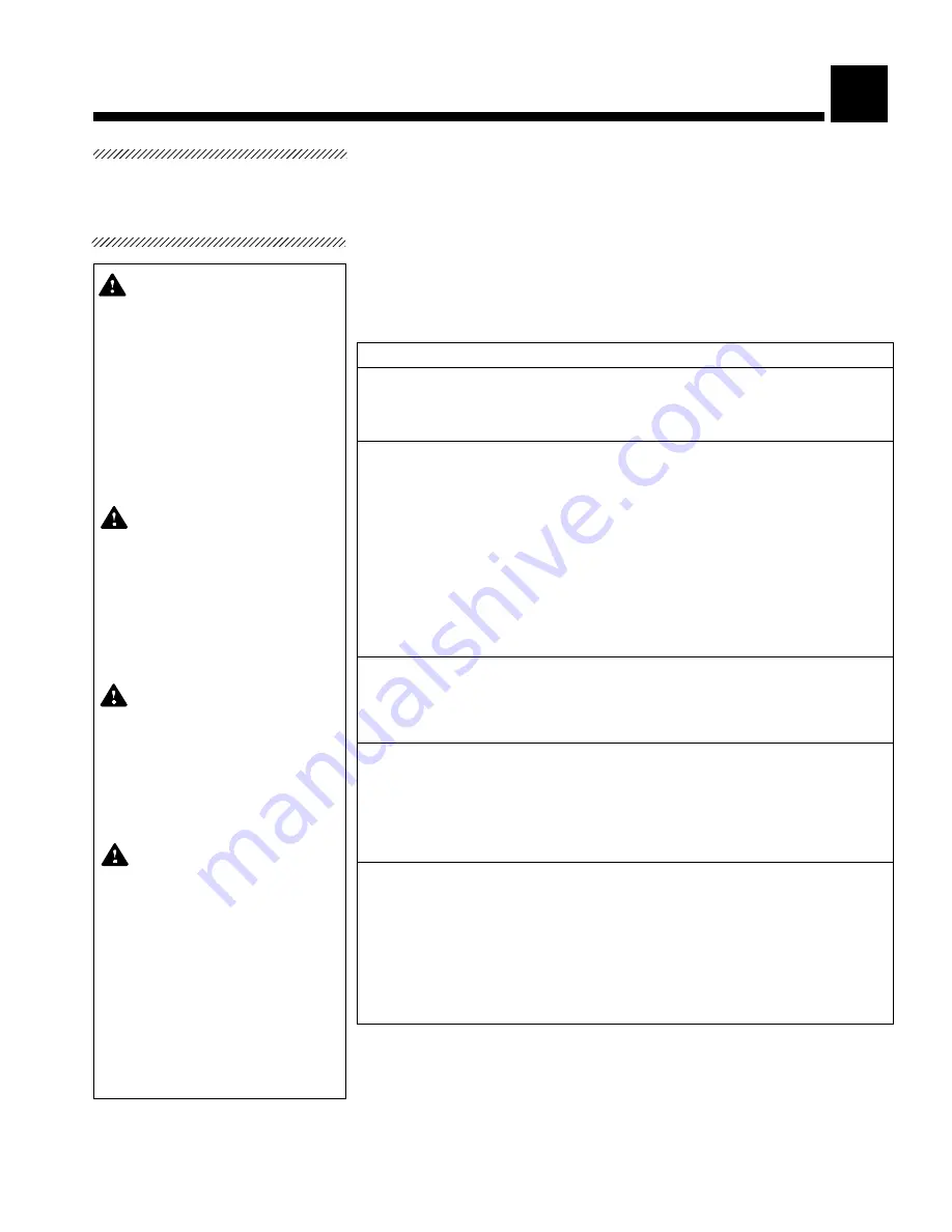
ROUTINE MAINTENANCE
Maintenance procedures described in Sections 5 and 7 should be performed
regularly at the intervals indicated, using the preventive schedule in Table 5-1
as a guide. Local conditions (amount of usage, etc.) may require more frequent
maintenance than indicated. Refer to Section 7 for list of replacement parts.
Maintain a record of all maintenance procedures performed on the unit.
If an operating problem occurs, refer to Section 6, Troubleshooting.
NOTE:
Never permit unqualified persons to service the light.
Table 5-1. Preventive Maintenance Schedule for Gemini Lighting System
Service Required
Minimum Frequency
1.0 Preparation for Preventive Maintenance
1.1 Discuss equipment with operators.
Each inspection
1.2 Follow appropriate safety procedures; prepare unit for PM.
Each inspection
2.0 Each Lighthead
2.1 Check lamp sockets and bulbs for deterioration.
Each inspection
2.2 Verify proper rotation of lighthead in yoke.
Each inspection
2.3 Verify proper rotation of yoke about the suspension arm.
Each inspection
2.4 Check the lens yoke/suspension arm attachement.
Each inspection
2.5 Verify lens is securely attached.
Each inspection
2.6 Check condition of lens. Clean/replace if needed.
Each inspection
2.7 Verify that sterile handle support is securely attached and
Each inspection
sterile handle properly threads onto support. Verify that
nonsterile handle is securely attached.
3.0 Each Suspension Arm Assembly
3.1 Check arm assembly for equal raise/lower forces and drift.
Each inspection
Adjust if needed.
3.2 Check yoke assembly for oil leakage.
Each inspection
4.0 Units with Centra Hub Mount
4.1 Check each horizontal arm assembly for drift. Level mount
Each inspection
or adjust break as needed.
4.2 Check that suspension tube is securely attached to arm
Each inspection
and support casting (refer to Section 5 in Maintenance
Manual).
5.0 Units with Track Mounting
5.1 Check each suspension arm assembly for lateral drift.
Each inspection
5.2 Verify that the suspension tube is securely pinned to the
Each inspection
carriage assembly and suspension arm fork.
5.3 Check carriage assembly for drift.
Each inspection
5.4 Check carriage wheels and lubricate.
Each inspection
5.5 Check trolley ducts and trolley for signs of dirt or pitting.
Each inspection
Preventive
Maintenance
Schedule
WARNING - PERSONAL
INJURY HAZARD:
Repairs
and adjustments should be
attempted only by experi-
enced technicians fully ac-
quainted with this equipment.
Use of inexperienced, un-
qualified persons to work on
the equipment or the instal-
lation of unauthorized parts
could cause personal injury
or result in costly damage.
WARNING - PERSONAL
INJURY HAZARD:
Do not at-
tempt to clean lighthead un-
less power is turned off at the
circuit breaker or fuse box.
For floor stand units, unplug
at receptacle. Make sure the
lighthead is cool before
touching.
WARNING - PERSONAL
INJURY HAZARD:
When re-
placing or removing lamp,
grasp the lamp by the ce-
ramic base and pry from the
socket. Do not pull on glass
portion of lamp as it may
break.
WARNING - ELECTRIC
SHOCK AND BURN HAZARD:
Disconnect all electrical in-
put to the lighting system
before servicing. Do not ser-
vice the lighting system un-
less all electrical input has
been properly locked out. Al-
ways follow OSHA lock-out/
tagout and electrical safety
related work practice stan-
dards. (See 29 CFR 1910.147
and .331 through .335.)
Содержание Gemini
Страница 3: ...iii Table of Contents Operator Manual 129360 627 This Page Intentionally Left Blank ...
Страница 6: ...vi 129360 627 Operator Manual Table of Contents This Page Intentionally Left Blank ...
Страница 8: ...1 2 129360 627 Operator Manual Listing of Warnings and Cautions This Page Intentionally Left Blank ...
Страница 16: ...4 4 129360 627 OperatorManual Operating Instructions This Page Intentionally Left Blank ...
Страница 22: ...5 6 129360 627 OperatorManual Operating Instructions This Page Intentionally Left Blank ...
Страница 24: ...6 2 129360 627 OperatorManual Operating Instructions This Page Intentionally Left Blank ...