


Temposonics
®
R-Series
V
POWERLINK
Operation Manual
I 14 I
Hydraulics sealing
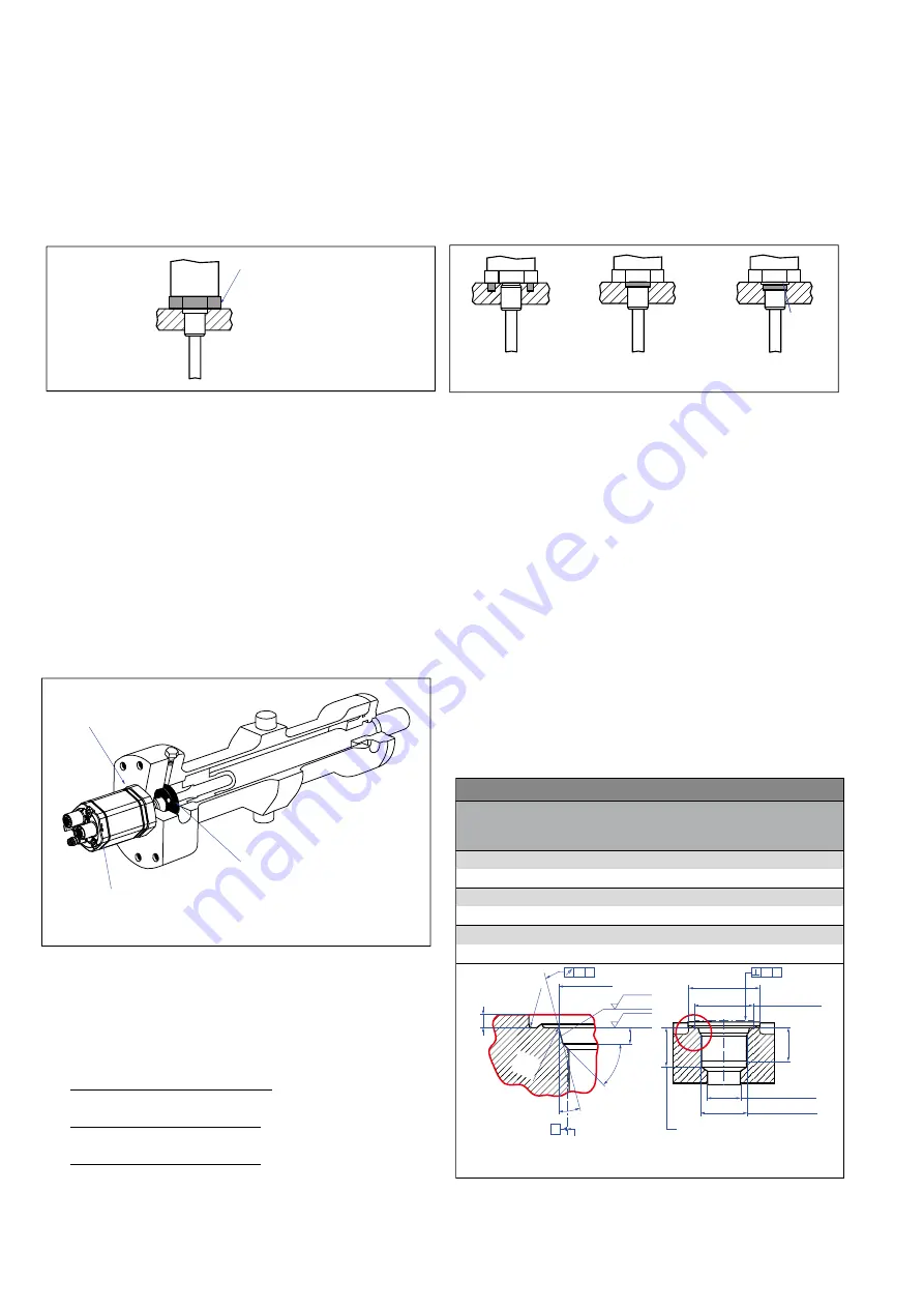
There are two ways to seal the flange contact surface (Fig. 10):
1. A sealing by using an O-ring (e.g. 22.4 × 2.65 mm (0.88 × 0.1 in.),
25.07 × 2.62 mm (0.99 × 0.1 in.)) in a cylinder end cap groove.
2. A sealing by using an O-ring in the undercut.
For threaded flange (¾"-16 UNF-3A):
O-ring 16.4 × 2.2 mm (0.65 × 0.09 in.) (part no. 560 315)
For threaded flange (M18×1.5-6g):
O-ring 15.3 × 2.2 mm (0.60 × 0.09 in.) (part no. 401 133)
For threaded flange (M22×1.5-6g):
O-ring 19.2 × 2.2 mm (0.76 × 0.09 in.) (part no. 561 337)
Installation of RH5 with threaded flange
Fix the sensor rod via threaded flange M18×1.5-6g, M22×1.5-6g or
¾"-16 UNF-3A.
Installation of a rod-style sensor in a fluid cylinder
The rod-style version has been developed for direct stroke
measurement in a fluid cylinder. Mount the sensor via threaded flange
or a hex nut.
• Mounted on the face of the piston, the position magnet travels
over the rod without touching it and indicates the exact position
through the rod wall – independent of the hydraulic fluid.
• The pressure resistant sensor rod is installed into a bore in the
piston rod.
• The base unit is mounted by means of three screws. It is the only
part that needs to be replaced if servicing is required, i.e. the
hydraulic circuit remains closed. For more information see chapter
"4.8 Replacement of base unit" on page 29.
Fig. 8: Mounting example of threaded flange
Fig. 9: Sensor in cylinder
In the case of threaded flange M18×1.5-6g or M22×1.5-6g, provide
a screw hole based on ISO 6149-1 (Fig. 11). See ISO 6149-1 for further
information.
• Note the fastening torque:
RH5-M: 65 Nm
RH5-S: 50 Nm
RH5-T:
55 Nm
RH5-J:
125 Nm
• Seat the flange contact surface completely on the cylinder
mounting surface.
• The cylinder manufacturer determines the pressure-resistant
gasket (copper gasket, O-ring, etc.).
• The position magnet should not grind on the sensor rod.
• The piston rod drilling
(RH5-M/-S/-T-A/-M/-V with rod Ø 10 mm: ≥ Ø 13 mm (≥ Ø 0.51 in.);
RH5-M/-S/-T-B with rod Ø 10 mm: ≥ Ø 16 mm (≥ Ø 0.63 in.);
RH5-J-A/-V with rod Ø 12.7 mm: ≥ Ø 16 mm (≥ Ø 0.63 in.))
depends on the pressure and piston speed.
• Adhere to the information relating to operating pressure.
• Protect the sensor rod against wear.
Fig. 10: Possibilities of sealing
for threaded flange with flat face 1. + 2.a. (RH5-J/-M/-S)
and with raised-face 2.b. (RH5-T)
Fig. 11: Notice for metric threaded flange M18×1.5-6g/M22×1.5-6g based on DIN ISO 6149-1
Notice for metric threaded fl anges
Thread
(d
1
×P)
d
2
d
3
d
4
d
5
+0.1
0
L
1
+0.4
0
L
2
L
3
L
4
Z°
±1
°
RH5-M-A/-M/-V
M18×1.5-6g
55
≥ 13
24.5 19.8 2.4 28.5 2
26 15°
RH5-M-B
M18×1.5-6g
55
≥ 16
24.5 19.8 2.4 28.5 2
26 15°
RH5-J-A/-V
M22×1.5-6g
55
≥ 16
27.5 23.8 2.4 28.5 2
26 15°
Ød
5
Ra 3.2
Ra 3.2
Pitch diameter
A
A
Thread
(d
1
× P)
Ød
3
(Reference)
A
Ød
2
Ød
4
(Gauging)
This dimension applies when
tap drill cannot pass through
entire boss.
≤ R0.4
R0.3 R0.1
Z°
45
° ±
5°
L
3
L
1
L
2
L
4
A
0.1
A
0.2
Controlling design dimensions are in millimeters
Fastening torque:
RH5-M: 65 Nm
RH5-S: 50 Nm
RH5-T: 55 Nm
RH5-J: 125 Nm
In the event of servicing, the sensor rod
with flange remains in the cylinder
Position magnet
Base unit
The sensor electronics housing
with sensing element can be replaced
Sealing via O-ring
in the flange undercut
Sealing via O-ring
in cylinder end cap groove
Raised-
face
Sealing via O-ring
in the flange undercut
1.)
2.a.)
2.b.)