background image

169

ASC200/ASC250

MAINTENANCE MANUAL

4

3

Every 2000 Hours or Every 2 Years

Every 2000 Hours or Every 2 Years

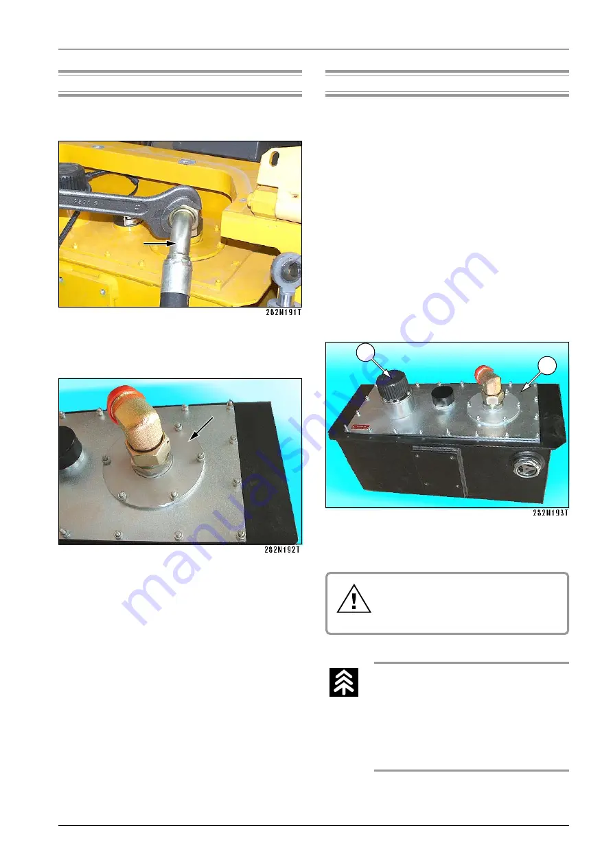
Dismantle suction hose.

Dismantle cover with suction strainer.

Dismantle the suction strainer from the suction pipe.
Wash the suction strainer and blow the strainer with
pressure air from inside.

Check the condition of the suction strainer; replace
the strainer in case of damaged filter part.

Check the inside of the tank. Carefully clean the bot-
tom and flush it with new oil if there are any impurities
on the bottom.

Reassemble and wipe the ”O” ring with clean oil.

NOTE

For easier cleaning it is possible to dismantle the whole
upper cover 3 with the filler 4. If you dismantled the whole
upper cover 3, use a new teflon sealing strip.

Drain oil after it has cooled
down below 50 °C (122 °F).

Follow the fire safety measures!

After disconnecting the hydraulic
circuits blind all holes with plugs.

Collect drained oil; do not leave it
soak into the soil.

Used oil is environmentally danger-
ous waste - have them liquidated.

Содержание ASC 200 Series

Страница 1: ...Operating manual E ASC 200 and ASC 250 CUMMINS TIER III 1 2008...

Страница 2: ...ations of figures are reserved All dimensions and weights are approximate and therefore not binding Ammann Czech Republic a s reserves the right to perform modifications without obligation to inform t...

Страница 3: ...y to provide the operator with these instructions and to ensure that he reads them carefully before using the road roller This aids training comprehension during the first use of the road roller Subse...

Страница 4: ...4 ASC200 ASC250...

Страница 5: ...5 ASC200 ASC250 NOTICE As used in this operating manual the terms right left front and rear indicate the sides of the machine moving forward...

Страница 6: ...kes 29 1 3 7 Steering 30 1 3 8 Vibratory Drum 30 1 3 9 Hydrostatic Drive of Travel 31 1 3 10 Hydrostatic Drive of Vibration 31 1 3 11 Hydraulic Oil Tank 32 1 3 12 Lifting and lowering of the Hood and...

Страница 7: ...ces 58 2 7 Controlling and operation of the machine 86 2 7 1 Starting the engine 86 2 7 2 Travel and reversing without vibrations 89 2 7 3 Travel with vibration 91 2 7 4 Stopping the machine and engin...

Страница 8: ...ng oil in the hydraulic tank 138 3 6 4 Crankcase breather tube 139 3 6 5 Checking of the condition ventilator and belt 140 3 6 6 Checking the vacuum valve of the air cleaner 141 3 6 7 Checking fuel le...

Страница 9: ...river s post 173 3 6 30 Exchanging the engine cooling liquid 174 3 6 31 Checking torsion vibration damper of the engine 176 3 6 32 Checking coolant in the drum 177 Maintenance As Needed 178 3 6 33 Exc...

Страница 10: ...10 ASC200 ASC250...

Страница 11: ...11 ASC200 ASC250 1 SPECIFICATION MANUAL ASC 200 and ASC 250 Cummins tier 3...

Страница 12: ...hickness of 40 cm 15 7 in after compaction loams up to the layer thickness of 70 cm 27 6 in and mixed soils up to the layer thickness of 90 cm 35 4 in It can be also used for pulverization and compact...

Страница 13: ...erial Number Engine CUMMINS Serial Number Please refer to the data in the table below always when approaching the dealer or the manufacturer Please fill in the following data see Pin label Label of th...

Страница 14: ...0 5 2 0 0 6 1 0 1 2 3 0 6 5 2 5 6 2 3 0 2 1 0 3 7 3 0 8 5 2 5 4 4 2 0 7 2 3 0 3 0 1 0 0 5 4 4 2 1 4 8 9 0 3 6 4 6 2 1 8 0 0 1 5 8 2 1 3 7 4 8 6 4 1 6 1 0 1 3 6 9 7 8 2 1 6 0 4 7 9 1 B D P 0 0 2 C S A...

Страница 15: ...2 8 8 5 2 6 D P 0 0 2 C S A 0 3 4 0 0 3 6 0 7 7 1 0 2 1 0 4 1 0 8 2 6 0 8 7 3 0 0 9 3 0 3 0 8 1 2 0 4 2 2 0 9 5 1 9 6 1 8 4 2 7 9 6 2 7 4 5 5 2 7 4 2 8 8 4 1 5 3 5 1 8 1 1 8 5 8 2 8 8 5 2 6 B D P 0 0...

Страница 16: ...S A 0 6 1 3 0 0 5 2 0 0 6 1 0 1 2 3 0 6 5 2 5 6 2 3 0 2 1 0 3 7 3 0 8 5 2 5 4 4 2 0 7 2 3 0 3 0 1 0 0 5 4 4 2 1 4 8 9 0 3 6 4 6 2 1 8 0 0 1 5 8 2 1 3 7 4 8 6 4 1 6 1 0 1 3 6 9 7 8 2 1 6 0 4 7 9 1 B D...

Страница 17: ...5 2 6 D P 0 0 2 C S A 0 3 4 0 0 3 6 0 7 7 1 0 2 1 0 4 1 0 8 2 6 0 8 7 3 0 0 9 3 0 3 0 8 1 2 0 4 2 2 0 9 5 1 9 6 1 8 4 2 7 9 6 2 7 4 5 5 2 7 4 2 8 8 4 1 5 3 5 1 8 1 1 8 5 8 2 8 8 5 2 6 B D P 0 0 2 C S...

Страница 18: ...S A D P 0 5 2 0 9 2 3 0 0 5 2 0 0 6 1 0 1 2 3 0 6 5 2 5 6 2 3 4 5 1 0 3 7 3 0 8 5 2 5 4 4 2 0 7 2 3 0 3 0 1 0 0 5 5 9 2 1 4 8 9 0 3 6 4 6 2 1 8 0 0 1 5 8 2 1 1 6 8 6 4 1 6 1 0 1 3 6 9 7 8 2 1 6 0 4 7...

Страница 19: ...5 2 6 C S A D P 0 5 2 0 3 4 0 6 5 6 0 7 7 1 0 2 1 0 4 1 5 1 3 6 5 1 8 3 0 5 9 3 0 3 0 8 1 2 0 4 2 2 0 9 5 1 9 6 1 2 8 5 2 7 9 6 2 7 4 5 5 6 8 4 2 2 0 5 1 5 3 5 1 8 1 1 8 5 8 2 8 8 5 2 6 S A B D P 0 5...

Страница 20: ...P 0 5 2 0 9 2 3 0 0 5 2 0 0 6 1 0 1 2 3 0 6 5 2 5 6 2 3 4 5 1 0 3 7 3 0 8 5 2 5 4 4 2 0 7 2 3 0 3 0 1 0 0 5 5 9 2 1 4 8 9 0 3 6 4 6 2 1 8 0 0 1 5 8 2 1 1 6 8 6 4 1 6 1 0 1 3 6 9 7 8 2 1 6 0 4 7 9 1 S...

Страница 21: ...C S A D P 0 5 2 0 3 4 0 6 5 6 0 7 7 1 0 2 1 0 4 1 5 1 3 6 5 1 8 3 0 5 9 3 0 3 0 8 1 2 0 4 2 2 0 9 5 1 9 6 1 2 8 5 2 7 9 6 2 7 4 5 5 6 8 4 2 2 0 5 1 5 3 5 1 8 1 1 8 5 8 2 8 8 5 2 6 S A B D P 0 5 2 C 0...

Страница 22: ...6 350 3 Operation weight with cab and protective frame ROPS according to ISO 6016 kg lb 20875 46020 20945 46175 to drum kg lb 14085 31052 14155 31206 to axle kg lb 6790 14969 6790 14969 Static linear...

Страница 23: ...g lb 7755 17097 7755 17097 Static linear load kg cm lb in 63 2 353 7 Operation weight with cab according to ISO 6016 kg lb 21775 48006 21845 48160 to drum kg lb 14015 30898 14085 31052 to axle kg lb 7...

Страница 24: ...drum kg lb 20135 44389 to axle kg lb 7990 17615 Operating weight according to EN 500 is weight of the machine with full operating liquid half filling of fuel water tank of sprinkling and operator s we...

Страница 25: ...t speed range work km h 1 0 2 5 0 2 5 MPH 0 1 55 0 1 55 2 0 2 85 0 2 85 0 1 77 0 1 77 3 0 3 0 0 3 1 0 1 86 0 1 92 2nd speed range transport km h 0 8 7 0 8 8 MPH 0 5 4 0 5 46 Theoretical gradability 1s...

Страница 26: ...0 1 74 0 1 74 3 0 3 1 0 3 2 0 1 92 0 1 99 2nd speed range transport km h 0 9 5 0 9 5 MPH 0 5 9 0 5 9 Theoretical gradability 1st speed range work 102 101 2nd speed range transport 21 21 Practical gra...

Страница 27: ...pproach angle front 30 30 rear 31 31 Transversal stability with cabin and ROPS frame straight frame static 39 39 full turn static 34 34 Max allowed transversal inclination without vibration 23 23 with...

Страница 28: ...l h gal US h ASC 200 21 5 5 7 ASC 250 22 2 5 9 Fuel pre filter Fleetguard FS 19732 Fuel cleaners Fleetguard 3957413 Oil cleaner Fleetguard LF 3970 Air cleaner Donaldson FRG G130120 Air filter element...

Страница 29: ...re on soil kPa PSI 344 49 8 ASC 250 Tire inflation kPa PSI 150 22 ASC 250 Tire size 23 5x25 thread NB38 EM 20 16PR MITAS Average contact pressure on soil kPa PSI 330 46 2 ASC 200 Tire inflation kPa PS...

Страница 30: ...ory Drum ASC 200 D ASC 200 PD Drum dia mm in 1700 67 1600 63 Drum dia over pads mm in 1840 72 5 Drum width mm in 2240 88 25 2240 88 25 Drum shell thickness mm in 45 1 77 30 1 18 Number of pads 150 Hei...

Страница 31: ...0303 ASC 250 Hydraulic pump of travel variable output with skew plate electrohydraulically controlled Sauer 90 R 100 Delivery per revolution cm3 cu in rev 100 6 08 Safety pressure MPa PSI 42 6090 Kon...

Страница 32: ...0433 Filter SF 56 48 Block of lifting Hytos 729 0030 Hydraulic cylinders of hood lifting 2x HM 25 18 320 Hydraulic cylinder of cab lifting HM 40 22 320 Hand pump Technometra RC 16 Hydraulic locks for...

Страница 33: ...to 25 C 13 F kg lb 2 x 600 2 x 1323 to 0 C 32 F kg lb 2 x 500 2 x 1102 They represent additional weight per separate order for ASC 200 They represent additional weight per standard order for ASC 250 1...

Страница 34: ...n transfered to the body measured according the EN 1032 on the sand base under the vibration travel aw 0 5 m s2 vectorial sum transfered to the hands measured according the ISO 5349 on the sand base u...

Страница 35: ...n ASC 200 600 26 ASC 250 705 27 8 Cutting depth mm in ASC 200 242 9 5 ASC 250 252 9 9 Weight of blade total kg lb 1080 2381 Fastened to the machine frame with 2 bolts M 24 x 120 8G 3 bolts M 24 x 140...

Страница 36: ...0 309 Attached to ROPS by 4 bolts M16x30 8G Tightening torque Nm in lb 165 1457 E ATC interaxle differential Control unit Sauer Susmic S1X 26G2 511982 Proportional valve Sauer 507832 24V Slope sensor...

Страница 37: ...37 ASC200 ASC250 SPECIFICATION MANUAL N s e t o...

Страница 38: ...38 ASC200 ASC250...

Страница 39: ...39 ASC110 ASC130 ASC150 ASC200 ASC250 2 OPERATING INSTRUCTIONS ASC 110 ASC 130 ASC 150 ASC 200 and ASC 250 Cummins tier 3...

Страница 40: ...40 ASC110 ASC130 ASC150 ASC200 ASC250...

Страница 41: ...s agents bearing power of soil inclination of the work area These facts must be communicated to the machine s operator designated to carry out the work It is necessary to issue a technological procedu...

Страница 42: ...nted with the rules listed in the Operation Manual for the machine must provide for the fire extinguisher to be checked regularly must store the Operations Manual and the Operations Diary in the defin...

Страница 43: ...driver must comply with all safety signs placed on the machine and keep them in legible state Before the start of operations the driver must become acquainted with the site its obstacles slopes ser vi...

Страница 44: ...ic roads The machine must be provided with proper signs Following operations the machine s defects and re pairs must be recorded in the operations diary The driver of the next shift must be made aware...

Страница 45: ...other machinery or vehicles near by except those that are participating in the operation operate the machine at a site which cannot be sur veyed by the driver and where people or property could be end...

Страница 46: ...eling Do not touch the rotating parts while the motor is still running Symbol located on the left side of the cooler 4 Coolant Risk of scald Do not open the lid of the expansion tank until the liquid...

Страница 47: ...anel under the left side door 10 Handbook Indication of a box containing the machine handbook Symbol located at the back of the seat 11 Hanging figure To lift machine binding means of sufficient capac...

Страница 48: ...der cabine 17 Danger of injury Danger of being wound by the belt symbol placed on the left side of the cooler 18 Electrical equipment Cover the electrical equipment when washing the machine symbol pla...

Страница 49: ...ASC150 ASC200 ASC250 OPERATING INSTRUCTIONS 21 Emergency exit symbol placed on the right window of the cabin 22 Sling Points The machine is to be rigged in these points Symbols located on the both sid...

Страница 50: ...n palm in the direction of the driver second arm akimbo Attention Both arms sideways raised horizontally palms forward Attention Danger Swinging motion of both of the arms with antebrachium from the p...

Страница 51: ...swinging movements of ante brachium towards the body and backward Low speed cruising backward away from me Both arms erected abreast bending across with palms away from the body short swinging moveme...

Страница 52: ...arms lifted forward bending across Mark the X distance between palms then the motion signal follows Engine start Circular motion of right hand s antebrachium with the fist closed Engine cut off Oscil...

Страница 53: ...correctly marked on the outside Do not allow storage in unmarked bottles and other containers to prevent confusion Particularly confusing food and drink is dangerous Should skin mucous membranes or e...

Страница 54: ...e so that the shock absorbing system is not loaded protect rubber components with a layer of special conservation preparation inflate tires to prescribed pressure and protect them against direct sunsh...

Страница 55: ...any parts were damaged during transport or are missing Inform the shipper of any discrepancies Before starting operations again wash off conservation with high pressured hot water with ordinary degre...

Страница 56: ...t observe national regulations and laws on waste disposal and protection of environment We recommend that you refer always to specialized companies authorized to deal with such cases the machine manuf...

Страница 57: ...4 Articulated joint 5 Tractor frame 6 Axle 7 Fuel tank 8 Batteries 9 ROPS frame 10 Hydraulic oil tank 11 Cabin 12 Hood 13 Engine 14 Hydraulic oil cooler 15 Liquid radiator 17 Driver s workplace 18 Pu...

Страница 58: ...58 ASC110 ASC130 ASC150 ASC200 ASC250 Controls and control devices 2 6 Controls and control devices...

Страница 59: ...t To Start indicator lamp engine heating 22 Battery charging signal lamp 23 Brake signal lamp 24 Idle neutral position signal lamp 25 Air filter signal lamp 26 ATC interaxle differential signal lamp 2...

Страница 60: ...2 6 Controls and control devices Layout of controls and cabin accessories 44 Windshield washer switch 45 Fan switch 46 Rear wiper switch 47 Front wiper switch 48 Cabin illumination 49 Vent jets 50 Su...

Страница 61: ...ting and lower ing of driver s stand and bonnet 57 50A fuse 58 Driver s seat 59 Box 60 Levers of lifting and lowering of cab and hood 61 Heat control 62 Heating vents 63 Manual hydro generator operati...

Страница 62: ...neu tral position At the same time it is only used as a operating brake of the machine The control is locked in the set position Signal lamp 24 will light up to indicate neutral position of the contr...

Страница 63: ...ed in pre selector 1 to 3 positions correspond to common working speeds used for compacting and are factory pre set The machine can reach the maximum towing power climbing capacity in position 3 NOTE...

Страница 64: ...64 ASC110 ASC130 ASC150 ASC200 ASC250 2 6 Controls and control devices...

Страница 65: ...Hydraulic oil thermometer 10 Indicates the hydraulic oil temperature during operation NOTE Top limit is 90 C for oils of viscosity grades HV 68 and HV 100 50 60 C 122 140 F is the optimum work ing tem...

Страница 66: ...66 ASC110 ASC130 ASC150 ASC200 ASC250 2 6 Controls and control devices...

Страница 67: ...en identified by engine ECM Troubleshooting switch 17 idle speed op tion The switch is in the middle position Turn it continuously any direction forward or backward to find defects according to flash...

Страница 68: ...68 ASC110 ASC130 ASC150 ASC200 ASC250 2 6 Controls and control devices...

Страница 69: ...7 7 NOTE Repair the defect as soon as possible WTS WAIT TO START indicator lamp 21 Heating before the starting of the engine Battery charging signal lamp 22 Indicates proper function of battery charg...

Страница 70: ...70 ASC110 ASC130 ASC150 ASC200 ASC250 2 6 Controls and control devices...

Страница 71: ...n the tank under the lower limit The machine and engine will automatically stop environmental protection NOTE It is possible to start engine only after repairing the defect and refilling oil in the hy...

Страница 72: ...72 ASC110 ASC130 ASC150 ASC200 ASC250 2 6 Controls and control devices...

Страница 73: ...iliary lights switch 34 Use the switch to turn on auxiliary lights The lamp in the switch indicates lights lit up Warning lights switch 35 Use the switch to turn on warning lights The flashing lamp in...

Страница 74: ...Apply traction slip control only for driv ing up to platforms of transporting vehi cles Selector 2 must be off while switch 38 is on At the same time vibration is locked Heating fan switch 39 positio...

Страница 75: ...hydraulic oil level signal lamp travel control neutral position signal lamp Fuse F4 7 5 A ATC interaxle differential Fuse F5 5 A fuel gauge revolution counter hour meter hydraulic oil thermometer char...

Страница 76: ...Sun shield 50 Move the shield vertically to adjust it Windshield washer switch 44 Use the switch to turn on front and rear washers at the same time Roof fan switch 45 Use this switch to turn on the r...

Страница 77: ...lded 90 de grees from A working position to B transporting position NOTE Keep rear mirrors clean and properly adjusted Battery disconnector 53 Use the disconnector 1 to disconnect battery O position e...

Страница 78: ...or belt 1 Driver must fasten the seat belt during drive Lifting and lowering driver s stand switch 54 Lifting and lowering bonnet switch 55 Press buttons 54 or 55 to turn on lifting or lowering Manual...

Страница 79: ...ary Seat spring stiffness adjustment turn the catch to adjust stiffness according to driver s weight indicator 1 between 50 and 130 kg 110 266 lb in 10 kg 22 lb increments Horizontal seat squab adjust...

Страница 80: ...he position You have to lift it to the top position first to be able to put it back to its lowest position Arm rest adjustment raise and turn the screw to cast down a raise the rest Adjust the seat be...

Страница 81: ...r another 5 seconds the roller brakes to a stop and the engine stalls For subsequent engine start the driver must sit down move the travel control device to the neutral position and switch on the brak...

Страница 82: ...50 2 6 Controls and control devices Heating vents 62 Tilt the vents to adjust amount of fresh air swivel to adjust direction Front and rear windshields are blown with hot air to avoid dewing NOTE Ensu...

Страница 83: ...ntrol lever 63 Use the lever to control manual hydro generator of lifting and lowering the cabin and bonnet Fire extinguisher 64 For instructions how to use the fire extinguisher see the label Get fam...

Страница 84: ...ontrol devices Washer tank 65 The tank is used for supplying solution to two pumps of windshield washers for front and rear washer jets NOTE Fill the tank with anti freeze solution before winter Bottl...

Страница 85: ...85 ASC110 ASC130 ASC150 ASC200 ASC250 OPERATING INSTRUCTIONS Storage compartment 67 Compartment for driver s personal belongings Connector 70 Use this connector for warning beacon...

Страница 86: ...ARNING Do not start longer than 30 seconds Wait for 2 minutes before next starting Repeat starting procedure 3 times at most then detect the cause in fuel sys tem Missing smoke in the exhaust pipe ind...

Страница 87: ...87 ASC110 ASC130 ASC150 ASC200 ASC250 OPERATING INSTRUCTIONS...

Страница 88: ...cable pole to the pole of the battery in the supporting machine 4 Connect the other terminal of the cable pole to the part of the started machine that is securely connected to the engine or connect t...

Страница 89: ...gine speed e g 1 800 min 1 RPM Check whether vibration is not on the signal lamp 28 must not be on use switch 6 to turn it off Release brakes of the machine with a switch 4 Signal lamp will go off Giv...

Страница 90: ...ne speed NOTE Selector 2 transport gear can be activated when driving on finished sur face It is possible to activate selector 2 while the machine is under load rabbit symbol will light up Should towi...

Страница 91: ...ange Use pre selector 40 to turn on vibration amplitude Use selector 8 to adjust maximum engine speed The switch 15 must be switched off Start moving and use switch 6 to turn on vibration Signal lamp...

Страница 92: ...ion signal lamp 28 will go off Use control 1 to stop the machine signal lamps 23 and 24 will light up Brake the machine with a switch 4 Press button 15 to adjust idling speed Turn the ignition key to...

Страница 93: ...to N position Brake the machine with switch 4 and turn off the key 9 to 0 position Use this way of stopping in case of defect when the machine cannot be stopped by moving travel control 1 to neutral p...

Страница 94: ...ctor Clean the machine from dirt scraper and tyres Check the whole machine and repair defects arisen during the operation Check the tyre pressure Secure wheels and drum with scotch blocks Lock covers...

Страница 95: ...d Example of flashing error code Flashing code consists of three digits Example code 123 signal lamp Yellow lamp 19 will flash red lamp 18 will flash the code after 1 2 sec Number 1 red will flash onc...

Страница 96: ...rotations sensor fails or the contact to the cell is broken the wheel will be unlocked automatically while driving after 5 seconds and will start turning The wheel will lock up again for five seconds...

Страница 97: ...97 ASC110 ASC130 ASC150 ASC200 ASC250 OPERATING INSTRUCTIONS 2 7 9 Blade Unlock the blade on both sides For locked secured blade For unlocked blade...

Страница 98: ...nd operation of the machine Start the engine Switch off the Idle switch 15 set maximum RPM 8 or those proportional to the subse quent output Switch off the gear selector 2 and choose a suitable range...

Страница 99: ...rame beam as related to the movable indicator with the blade 94 and remember this information This is then the basic position of the blade Return the controller pedal to 0 position and start driving T...

Страница 100: ...tion I blade moves down position II blade moves up position III blade is in floating position Volume of the shovelled material can be corrected by lowering the blade blade lever in I position or by li...

Страница 101: ...he lever to A position lifting Insert the lever to the pump and lift the driver s stand Move the lever to B position lowering and pump Screw the driver s stand in after lowering If the driver s stand...

Страница 102: ...hydro generator Lifting and lowering using electric hydraulic pump op tional Remove nuts of the driver s stand Connect electric system by turning the battery discon nector 1 Press and hold button 2 li...

Страница 103: ...e the manual hydro generator to perform lifting and lower ing Open the cover 1 on the left side under the driver s stand Take out the pump lever 2 Driver s stand Remove nuts of the driver s stand Push...

Страница 104: ...the driver s stand Screw the driver s stand in after lowering If the driver s stand is not screwed in prop erly the machine may over turn and cause lethal injuries Bonnet Push the sliding valve 3 on...

Страница 105: ...ween worksites if not using public roads NOTE When transporting the machine on fin ished roads use transport gear activate selector 2 In case of long distance transport make an hour cooling break afte...

Страница 106: ...mmunication signals he she must stand all the time on the same location away from the machine and the trans porting vehicle He she must be within the field of driver s vision visual contact for all th...

Страница 107: ...hine Use drive up ramps or crane to load the machine to a transporting vehicle The roller is equipped with lifting eyes for loading by crane Lock the joint against movements prior to lifting the rolle...

Страница 108: ...in Do not step under the hang ing load Return the safety arm and blocks to default positions after loading is complete Observe appropriate regula tions while loading and unloading the machine Use appr...

Страница 109: ...t dismantle cabin and ROPS frame Dismantling ROPS Hang the frame by lifting eyes Dismantle bolts and remove the frame Dismantling cabin Remove bolts 1 fastening the cabin to the platform Disconnect el...

Страница 110: ...he frame of drum Options Pin is also used for front towing lug on the crossbar of the front frame It is forbidden to use the machine for towing towed vehicles e g tanks compres sors house trailers etc...

Страница 111: ...1 4 3 1 3 Releasing drum and wheels for ASC 110 ASC 130 ASC 150 Release all multi plate brakes to avoid slipping of drum and wheels Release hose 1 in clip 2 Disconnect hose 3 from tube 4 Connect hose...

Страница 112: ...ver on the left side under cabin Take out the lever 68 under the driver s stand Insert the lever 68 into the manual hydro generator and pump until the machine is unbraked for towing now Releasing brak...

Страница 113: ...t hose 1 from hose 3 in the quick coupling 2 Connect hose 3 back to tube 4 Fix hose 1 in clip 2 Turn the ignition key to I position and check signal lamp of brake 23 switched off NOTE During towing le...

Страница 114: ...enerator lever 63 to the holder under the driver s stand WARNING During towing leakage may cause pres sure in brakes decrease When towing check brakes for heating due to insuffi cient brake release To...

Страница 115: ...stance if the engine is running and the driving unit and steering are functional The drive on the towed roller must steer the roller in the dragging direction If the engine is stopped Avoid damaging i...

Страница 116: ...m mended oil for the specific gearbox operating temper ature range Use winter fuel Check battery charge Good battery condition is essential for good starting under low temperature You can lower the th...

Страница 117: ...around 90 C 194 F it is recommended to exchange hydraulic oil for oil a grade higher of kinematic viscosity 100 mm2 s e g BP BAR TRAN HV 100 ESSO UNIVIS N100 etc NOTE When working under extreme condi...

Страница 118: ...500 1640 3 1000 3281 6 1500 4921 10 2000 6562 15 2500 8202 21 3000 9843 28 If the engine produces black exhaust fumes in higher altitude contact a service organisation of the engine manufacturer that...

Страница 119: ...F add extra weight in the form of solution of water and copper sulphate CuSO4 5H2 O bluestone For one tyre mix 500 l 132 US gal of water and 0 17 kg 0 4 lb of copper sulphate CuSO4 5H2 O Fill tyres wi...

Страница 120: ...m both sides lift the rear part of the roller and release brake of wheel hydromotors see chapter 2 9 1 Rotate tyres so that valves 1 are at top positions Unscrew valves Warning The solution will squir...

Страница 121: ...121 ASC110 ASC130 ASC150 ASC200 ASC250 OPERATING INSTRUCTIONS N s e t o...

Страница 122: ...122 ASC110 ASC130 ASC150 ASC200 ASC250 N s e t o...

Страница 123: ...123 ASC200 ASC250 3 MAINTENANCE MANUAL ASC 200 and ASC 250 Cummins tier 3...

Страница 124: ...124 ASC200 ASC250...

Страница 125: ...se recommended fills Operations performed while the engine is running adjusting must be performed with anoth er person present This person must have immediate access to the emergency stop and must be...

Страница 126: ...inal properly marked containers Avoid storing these ma terials in unmarked bottles or other containers becau se of risk of possible substitutions Possible substi tution of food and beverages is partic...

Страница 127: ...F NOTE Exceeding of the lower temperature limit does not dam age the engine it may only cause starting problems It is suitable to use general purpose multi grade oil in order that oil need not be exch...

Страница 128: ...SHELL Glycoshell AF 511 S TEXACO HAVOLINE Antifreeze Coolant AFC CASTROL ANTIFREEZE MB WARNING Do not use more than 50 of antifreeze in the coolant unless absolutely neces sary Never use a ratio high...

Страница 129: ...NG Water content condensation water in oil must not exceed the limit of 0 1 Operating fluid must be checked by taking samples in regular intervals see the chart When filling older machines with syn th...

Страница 130: ...P E R A E G O P Y H L O R T S A C Y O P Y H Y O P Y H N O R V E H C R A E G L A S R E V I N U E T N A C I R B U L R A E G L A S R E V I N U E T N A C I R B U L F L E 8 F L E S N A R T 8 F L E S N A R...

Страница 131: ...n i o j s g n i r a e b t n i o J r e d n i l y c g n i r e e t s d n a 6 2 3 r e t p a h c o t g n i d r o c c a e s a e r g c i t s a l P d e r i u q e r s a m e t s y s g n i l o o c e n i g n E t...

Страница 132: ...132 ASC200 ASC250 3 4 Lubrication and Maintenance Chart...

Страница 133: ...133 ASC200 ASC250 MAINTENANCE MANUAL...

Страница 134: ...134 ASC200 ASC250 3 5 Lubrication Chart...

Страница 135: ...ons of hydraulics etc should be tightened with torque according to tables in chapter 3 6 38 unless a different value is listed for the particular operation NOTE Follow the instructions given in the ma...

Страница 136: ...the filler plug through the oil filler Wait approx 1 min until the level is stable and check again Refill the identical type of oil Use oils according to chapter 3 2 1 Check the engine for leakage rep...

Страница 137: ...dentical basis according to chapter 3 2 3 Do not add additives eliminating untight ness of the cooling system to the engine cooling liquid Do not refill cold cooling liquid into hot engine Engine cast...

Страница 138: ...wer edge of the MIN oil level indicator the engine will automatically stop and signal lamp 27 will light up NOTE In case of more extensive losses find the location of hydraulic system leaks and repair...

Страница 139: ...50 MAINTENANCE MANUAL Every 20 Hours or Daily Every 20 Hours or Daily 3 6 4 Crankcase breather tube Inspect the breather tube for sluge debris or ice the tube Note Inspect the tube more frequently in...

Страница 140: ...isually In case of any damage e g missing parts of the material cracks changes in shape etc replace the ventilator Check visually the belt for its deterioration Traverse across the belt width cracks a...

Страница 141: ...e the trapped dust by pushing Every 20 Hours or Daily Every 20 Hours or Daily NOTE Collected dust is stored in the dust valve and automa tically emptied during the machine operation If the machine is...

Страница 142: ...use open fire when working WARNING Do not use up the fuel tank In such case the whole fuel system must be de aerat ed which is rather tedious operation Use clean and recommended fuel only according to...

Страница 143: ...the valve counterclockwise approximately 31 2 turns until the valve drops down 25 mm 1 in and draining occurs and let fuel drain until clean fuel starts to drain WARNING If you drained more than 6 cl...

Страница 144: ...ely Announce starting the engine by the acoustic signal Check before starting of the engine that nobody is endan gered Give the acoustic signal before starting driving the machine and wait for period...

Страница 145: ...E MANUAL Every 100 Hours Every 100 Hours 3 6 10 Checking the tyre pressure Check the pressure in cold tyres by air pressure meter Keep the tyre pressure at 150 kPa 22 PSI WARNING Rotate tyres so that...

Страница 146: ...heck the tightness of engine inlet piping Check for any damage of the rubber hose of the inlet piping leading from the filter and for missing clam ping clips Check again tightness between the bonnet 2...

Страница 147: ...missing parts of the material cracks changes in shape etc replace the ventilator Lift the belt tensioning pulley using the lever and remove the belt Check visually the belt for intersecting crakcks Tr...

Страница 148: ...for instance by blowing the radiators throu gh with pressure air steam or warm water according to chapter 3 6 34 Every 250 Hours or Once in 3 Months Every 250 Hours or Once in 3 Months 3 6 13 Checking...

Страница 149: ...al cells using a refractometer or hydrometer Compare measured values with the chart NOTE Check the level using a glass tube Should the machine not be used during winter period for couple of weeks dism...

Страница 150: ...sh injured spots with soap water or with solution of soda and water as soon as possible Then seek medical advice Do not eat drink and smoke during operation Wash your hands and face care fully with so...

Страница 151: ...Set engine speed to increased speed of approx from 1 500 rpm to max 2 000 rpm Dismantle the engine suction cover Shortly cover the inlet opening of the air cleaner on the engine bonnet After such cov...

Страница 152: ...t firm surface Stop the engine and disconnect electric system using the isolating master switch Remove the caps on the grease nipples Successively mount the grease nipple of pressure lubricator and co...

Страница 153: ...MANUAL Every 250 Hours or Once in 3 Months Every 250 Hours or Once in 3 Months Hydraulic cylinders of bonnet lifting upper pins 2x lower pins 2x Hydraulic cylinder of driver s post lifting lower pins...

Страница 154: ...l Operations of Maintenance Every 250 Hours or Once in 3 Months Every 250 Hours or Once in 3 Months Bonnet hinges pins pins 2 x Front pins of cabin attachment pins 2 x NOTE Use only recommended lubric...

Страница 155: ...ition according to fig NOTE To better ilustrate the position of plugs the drum frame was not installed Clean the area around the checking plug 1 Unscrew the plug 1 and check the oil level The oil leve...

Страница 156: ...e position according to fig Clean the area around the checking plug Unscrew the plug and check the oil level The oil level must reach the checking opening or slightly flow out Refill oil through the c...

Страница 157: ...er and refill oil through the filling plug 2 if necessary Clean the plugs and mount again Check tightness of the gearboxes Do not touch the gearbox and adjacent parts if they are hot Every 250 Hours o...

Страница 158: ...lean the contact area of the filter sealing Take a new filter and fill it with clean engine oil Wipe the sealing with oil NOTE Drain the oil after stopping the operation immediately when is temperatur...

Страница 159: ...ess of drain plug and filter Stop the engine wait for approx 5 min until oil runs down to the engine sump Then check the level with oil dipstick NOTE Do not tighten the filter too tight the thread and...

Страница 160: ...a around the fuel filter head remove filter Every 500 Hours or Once in 6 Month Every 500 Hours or Once in 6 Month Lubricate the O ring seal of new filter with lubricating oil Tighten 3 4 turn after ga...

Страница 161: ...nnect connector of sensor se parator water Every 500 Hours or Once in 6 Month Every 500 Hours or Once in 6 Month Refuel with hand pump in fuel pre filter Note I is not necessary to vent air from the h...

Страница 162: ...Month Every 500 Hours or Once in 6 Month 3 6 21 Checking cooling liquid Check the concentration of anti freeze agent in coo ling liquid using a refractometer NOTE Check the cooling liquid always befo...

Страница 163: ...arm does NOT contact bump stop of the bush Replace the belt if it makes a contact When the arm stops continue to contact bump stop of the bush replace the tensioner Lift the belt tightening pulley us...

Страница 164: ...the upper plug 2 until the level reaches the opening or until it starts flowing out Mount back the upper plugs 2 replace damaged plug sealings NOTE Perform the first oil exchange after reaching 100 o...

Страница 165: ...the opening or slightly flow out Mount the plugs 1 and 2 replace damaged plug sealings Clean the area around plugs Put appropriate vessel under the drain plug 3 Unscrew all plugs 1 2 3 and let oil dra...

Страница 166: ...condition of metal rubber mountings and bonding of metal with rubber Drum damping system left side Drum damping system right side Front metal rubber mountings driver s post Rear metal rubber mounting...

Страница 167: ...ous fouling dismantle the batte ries and the tank cover 1 Check and clean the inside of the tank Insert a new sealing teflon strip between the cover and the tank and screw in the cover Mount the batte...

Страница 168: ...drain plug Unscrew all plugs and let oil drain Mount the drain plug 3 after draining is finished Refill recommended oil to the edge of the checking opening 2 through the filler 1 Mount remaining plugs...

Страница 169: ...e inside of the tank Carefully clean the bot tom and flush it with new oil if there are any impurities on the bottom Reassemble and wipe the O ring with clean oil NOTE For easier cleaning it is possib...

Страница 170: ...roperly Filling the hydraulic circuit Use a filling device with the following parameters min pressure 6 MPa 870 PSI filtering property 3 to 10 m Open the cover on the right side under the cabin and re...

Страница 171: ...en inner part of a unit hydromotors hydro generators were destroyed or after a considerable repair of hydraulic system Clean and rinse the hydraulic tank be fore assembling a new unit Exchange filter...

Страница 172: ...m perature reached 50 through 60 C 122 140 F Dismantle the filter container 2 Take out the filter element Carefully clean the filter container Clean the contact surface of the filtration block from th...

Страница 173: ...ner of lifting and lowering of the bonnet and the driver s post NOTE Clean the strainer when exchanging hydraulic oil Unscrew bolts 1 take out the unit from the bottom of the tank Remove the suction s...

Страница 174: ...equaliser reservoir Do not dismantle the pressure plug before the temperature of cooling liquid falls lower than to 50 C 122 C Beware of gushing of the coolant and scalding when opening the pressure...

Страница 175: ...before the temperature of cooling liquid falls lower than to 50 C 122 C Beware of gushing of the coolant and scalding when opening the pressure plug NOTE Use cooling liquid according to chapter 3 2 3...

Страница 176: ...1 16 in it is necessary to exchange the damper Check whether the rubber component 3 is not higher or lower above the level of metal parts 1 and 2 by more than 3 18 mm 1 8 in If the limit is exceeded e...

Страница 177: ...uid with clean water The solution may not spill over metal parts and electrical wir ing This solution may not be used in the motor radiator Dehydrated Calcium chloride CaCl2 is to be added to water no...

Страница 178: ...r cleaner NOTE The air cleaner contains the main and safety elements NOTE If signal lamp 25 lights up the both elements must be exchanged Lift the bonnet to the limit position See Operating instructio...

Страница 179: ...Replace both elements after 1 year of service at the leatest Use original elements only When washing the machine make sure water cannot pour into the air cleaner In case of absorbing water exchange m...

Страница 180: ...liquid and hydraulic oil Clean it using pressure air or pressure water steam Cleaning direction is from the ventilator side NOTE Do not use cleaner with too high pres sure so as not to damage radiator...

Страница 181: ...alternator etc Disconnect batteries using the isolating master switch Work with stopped engine Do not use aggressive and highly inflam mable cleaning agents e g petrol or highly inflammable materials...

Страница 182: ...e range of oval openings of the holders 2 due to the wear of the scrap ers dismantle the scraper 3 and move it closer to the drum by one hole Scrapers for the taper foot drum Loosen bolts 1 and move i...

Страница 183: ...4 1 7 2 9 9 1 0 1 M 8 4 4 5 3 7 6 4 9 4 5 2 1 x 0 1 M 8 3 0 8 2 4 5 8 9 3 2 1 M 3 8 2 1 6 7 1 1 2 6 8 5 2 1 x 2 1 M 6 6 7 8 4 4 9 3 9 6 4 1 M 2 3 1 3 7 9 5 8 1 4 6 3 1 5 1 x 4 1 M 6 0 1 2 8 7 8 4 1 1...

Страница 184: ...x 4 1 M 8 8 3 0 3 5 4 8 2 2 2 3 3 9 1 5 1 x 6 1 M 8 5 4 8 3 2 5 3 3 8 2 8 3 0 1 2 2 5 1 x 8 1 M 0 1 1 5 3 4 8 5 8 3 2 3 3 4 2 1 4 2 5 1 x 0 2 M 2 1 8 5 0 5 5 6 3 4 7 3 8 4 7 2 5 1 x 2 2 M 4 1 4 7 0 6...

Страница 185: ...6 1 M 0 6 4 4 5 1 x 8 1 M 0 6 4 4 5 1 x 0 2 M 0 4 1 3 0 1 5 1 x 2 2 M 0 4 1 3 0 1 5 1 x 6 2 M 0 2 2 2 6 1 5 1 x 7 2 M 0 5 2 4 8 1 5 1 x 3 3 M 0 0 4 5 9 2 5 1 x 2 4 M 0 0 6 3 4 4 5 1 x 8 4 M 0 0 8 0 9...

Страница 186: ...186 ASC200 ASC250 3 6 Individual Operations of Maintenance...

Страница 187: ...ions given in the operation and mainte nance manual for the machine and engine If you cannot identify the cause contact a ser vice department of an authorised dealer or the manufacturer NOTE Troublesh...

Страница 188: ...of front headlights S5 Switch of rear headlights S6 Switch of warning lights S7 Change over switch of direction lights S8 Switch of safety beacon S9 Push button of horn S11 Push button of emergency b...

Страница 189: ...189 ASC200 ASC250 MAINTENANCE MANUAL...

Страница 190: ...190 ASC200 ASC250 3 8 Appendixes...

Страница 191: ...191 ASC200 ASC250 MAINTENANCE MANUAL MAINTENANCE MANUAL...

Страница 192: ...uction strainer HYTOS 15 Block of filter HYTOS 16 Filler ARGO 17 Hydraulic tank float 18 Combined cooler EMMEGI 18 One way valve HYTOS 20 Thermoregulator 21 Check point STAUFF 22 Quick release couplin...

Страница 193: ...193 ASC200 ASC250 MAINTENANCE MANUAL MAINTENANCE MANUAL...

Страница 194: ...tion strainer HYTOS 15 Block of filter DONALDSON 16 Filler ARGO 17 Hydraulic tank float 18 Combined cooler EMMEGI 18 One way valve HYTOS 20 Thermoregulator 21 Check point STAUFF 22 Quick release coupl...

Страница 195: ...195 ASC200 ASC250 MAINTENANCE MANUAL MAINTENANCE MANUAL...

Страница 196: ...196 ASC200 ASC250 N s e t o...

Страница 197: ...197 ASC200 ASC250 MAINTENANCE MANUAL N s e t o...

Страница 198: ...N s e t o...

Отзывы: