Goliath PCI Pentium Pro EISA System User’s Guide
16
Step 2 Configure CPU,
Continued
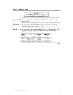
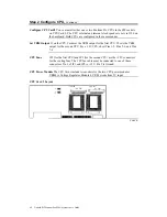
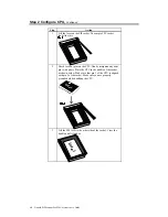
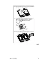
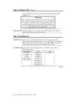
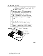
Insert the CPU Cards in the baseboard after installing the baseboard in the
computer case.
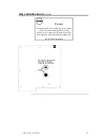
Warning
Make sure that you insert and remove the CPU Cards vertically
in and out of the sockets. Do not move the CPU Cards from side
to side. Make sure the CPU Card is perpendicular to the base
board. Insert pressure directly downward when installing the
CPU Cards. When removing a CPU Card, pull the card straight
up. Do not move it from side to side.
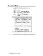
Using One CPU Card If installing CPU Card 1 only, insert the Terminator Card in the CPU
Card 2 socket. Do not use CPU Card 2 alone.
Step 3 Install Memory
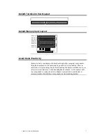
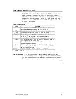
System Memory System memory for the Goliath is mounted on the memory card, which
supports up to 1 GB of system memory. Use 60 ns Fast Page ECC 3.3V 168-pin
ECC buffered memory module fast page mode or EDO DIMMs (Dual Inline
Memory Modules). The memory card has eight 168-pin sockets.
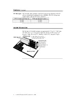
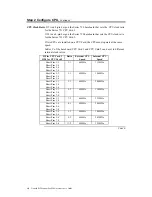
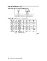
Set DRAM Voltage J11 and J12 are 20-pin jumpers that set the DRAM voltage. Only 3.3V
memory can be used.
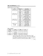
Type of Memory
J11
J12
3.3V 60 ns
Fast Page Mode
(or EDO)
x 72 ECC
Buffered Memory
Module DIMMs
Short Pins 1-2
Short Pins 3-4
Short Pins 5-6
Short Pins 7-8
Short Pins 9-10
Short Pins 11-12
Short Pins 13-14
Short Pins 15-16
Short Pins 17-18
Short Pins 19-20
All OPEN
Cont’d
Содержание Goliath
Страница 1: ...Goliath PCI Quad Pentium Pro EISA System User s Guide MAN 730 6 7 96 ...
Страница 45: ......
Страница 71: ...Goliath PCI Pentium Pro EISA System User s Guide 66 ...
Страница 77: ...Goliath PCI Pentium Pro EISA System User s Guide 72 ...
Страница 78: ...Chapter 3 Programming the Flash ROM 73 A Mechanical Drawings ...
Страница 79: ...Goliath PCI Pentium Pro EISA System User s Guide 74 ...
Страница 80: ...Chapter 3 Programming the Flash ROM 75 ...


