Chapter 1 Hardware Installation
37
Step 10 Attach IDE
IDE Drives
Set the Onboard IDE option to Primary in Peripheral Setup to enable onboard
IDE.
Important
J20 must be OPEN.
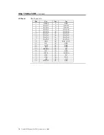
Attach IDE Cable J2 is the IDE (Integrated Drive Electronics) hard disk drive connector. The
primary master and the primary slave IDE drives are connected by cable to J2,
as shown below.
J2 is a 40-pin dual-inline berg that connects an ATA IDE drive to the primary
onboard IDE connector. This baseboard supports IDE Modes 0, 1, 2, 3, and 4,
IDE prefetch, LBA (Logical Block Address) mode, high capacity drives (over
528 MB), 32-bit data transfer, and fast IDE transfer. These IDE features are
configured in Peripheral Setup in the WINBIOS Setup utility. Disable the
onboard IDE interface in Peripheral Setup to use an EISA ESDI, RLL, MFM,
or SCSI hard disk drive.
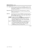
J21 IDE DREQ J21 is a 2-pin berg that enables the IDE DREQ. The settings are:
J21 Setting
IDE DREQ
Shorted
Enabled
OPEN
None
Cont’d
Содержание Goliath
Страница 1: ...Goliath PCI Quad Pentium Pro EISA System User s Guide MAN 730 6 7 96 ...
Страница 45: ......
Страница 71: ...Goliath PCI Pentium Pro EISA System User s Guide 66 ...
Страница 77: ...Goliath PCI Pentium Pro EISA System User s Guide 72 ...
Страница 78: ...Chapter 3 Programming the Flash ROM 73 A Mechanical Drawings ...
Страница 79: ...Goliath PCI Pentium Pro EISA System User s Guide 74 ...
Страница 80: ...Chapter 3 Programming the Flash ROM 75 ...

