Chapter 1 Hardware Installation
11
Step 2 Configure CPU,
Continued
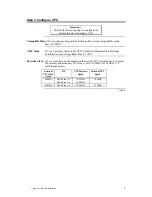
Configure CPU Card 1 You can install either one or two Pentium Pro CPUs in the ZIF sockets
on CPU Card 1. The CPU external and internal clock speeds are set via J15 on
the baseboard, as described on the previous screen. JP3 must always have a
shorting bridge.
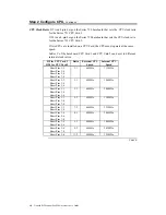
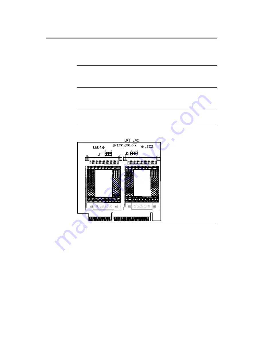
Set VRM Output J1 on the CPU Cards set the VRM output for the first CPU. J2 sets the VRM
output for the second CPU. For a 3.3V CPU, short Pins 1-2, Pins 5-6, and Pins
7-8.
CPU Fans
JP1 (for the first CPU) and JP2 (for the second CPU) are the +12V connectors
for the cooling fans. The CPU fan cable must be connected to one of these
connectors. Pin 1 of JP1 and JP2 is +12V. Pin 2 is Ground.
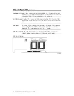
CPU Power Module The CPU Cards include two sockets for the two CPU power modules.
VRM8 is Voltage Regulator Module 8. VRM works from 5V input.
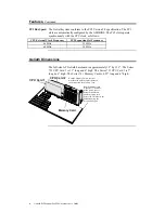
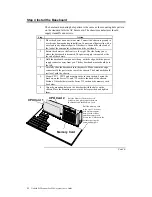
CPU Card Layout The CPU Card 1 layout is shown below.
Cont’d
Содержание Goliath
Страница 1: ...Goliath PCI Quad Pentium Pro EISA System User s Guide MAN 730 6 7 96 ...
Страница 45: ......
Страница 71: ...Goliath PCI Pentium Pro EISA System User s Guide 66 ...
Страница 77: ...Goliath PCI Pentium Pro EISA System User s Guide 72 ...
Страница 78: ...Chapter 3 Programming the Flash ROM 73 A Mechanical Drawings ...
Страница 79: ...Goliath PCI Pentium Pro EISA System User s Guide 74 ...
Страница 80: ...Chapter 3 Programming the Flash ROM 75 ...

