Chapter 1 Hardware Installation
31
Step 6 Attach Connectors,
Continued
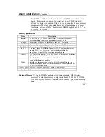
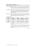
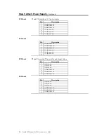
Connect Mouse Cable The mouse connector (J10) is a 10-pin berg. The mouse cable is the same
as the serial cable in the Goliath baseboard. Two serial cables are shipped with
the baseboard. Use one of these cables for the mouse.
Pin
Description
Pin
Description
1
Mouse Clock
2
N/C
3
N/C
4
N/C
5
N/C
6
VCC
7
N/C
8
Mouse Data
9
Ground
10
N/C
Connectors
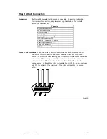
When connecting chassis connectors to the baseboard, make sure to connect the
correct connector end. Most connector wires are color-coded. Match the color
of the wires leaving the switch or LED to the same pin on the connector end.
There may be more than one connector with the same color-coded wires. If so,
follow the wire to the switch or LED. Pin 1 is always indicated on the
baseboard.
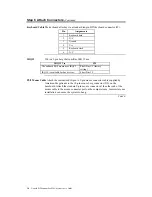
J27 Reset
J27 is a two-pin single-inline berg that is attached via a cable to an externally-
mounted reset switch. When the reset switch is pressed, the system performs a
hard reset. Pin 2 is ground and Pin 1 is Hard Reset.
Cont’d
Содержание Goliath
Страница 1: ...Goliath PCI Quad Pentium Pro EISA System User s Guide MAN 730 6 7 96 ...
Страница 45: ......
Страница 71: ...Goliath PCI Pentium Pro EISA System User s Guide 66 ...
Страница 77: ...Goliath PCI Pentium Pro EISA System User s Guide 72 ...
Страница 78: ...Chapter 3 Programming the Flash ROM 73 A Mechanical Drawings ...
Страница 79: ...Goliath PCI Pentium Pro EISA System User s Guide 74 ...
Страница 80: ...Chapter 3 Programming the Flash ROM 75 ...

