Rev. 5
157
Appendix
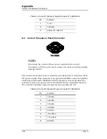
Quench I/O Connector
which the input is connected be galvanically isolated from any
external circuitry.
It is recommended that the external quench detection input be driven by
the contacts of a low level dry contact relay, which will galvanically isolate
the input from all other circuitry.
When the external quench detection input pins (pins 4 and 5 of the Quench
I/O connector) are shorted together, it is the same as if an Model 430
Programmer internal quench detection occurred. Refer to section 3.15 on
A.6.2
External Rampdown Input
When enabled
1
, the external rampdown input initiates a rampdown of the
magnetic field of the magnet when triggered.
Caution
The external rampdown input is a dry contact input, not
galvanically isolated from the Model 430 Programmer internal
circuitry. To avoid noise problems and potential damage to the
Model 430 Programmer, it is very important that the dry contacts to
which the input is connected be galvanically isolated from any
external circuitry.
It is recommended that the external rampdown input be driven by the
contacts of a low level dry contact relay, which will galvanically isolate the
input from all other circuitry.
When the external rampdown input pins (pins 6 and 7 of the Quench I/O
connector) are shorted together for more than 10 milliseconds, the Model
430 Programmer enters external rampdown mode. If the magnet is in
driven mode, the Model 430 Programmer ramps the magnet field/current
to zero. If the magnet is in persistent mode, the Model 430 Programmer
ramps the power supply to match the persistent magnet current, turns on
the persistent switch heater, waits the specified heated time and then
ramps the magnet field/current to zero.
This function may be used with an AMI Model 134 or 135 Liquid Helium
Level Instrument. The Level instrument has a NO relay associated with
the low level condition and this contact closure can be connected to the
External Rampdown Input so that when a low helium level occurs in a
system, the magnet is safely and automatically ramped down, preventing
a magnet quench. AMI offers a cable for this purpose or the user can make
Содержание 05100PS-430-601
Страница 2: ......
Страница 10: ...x Rev 5 List of Figures ...
Страница 12: ...xii Rev 5 List of Tables ...
Страница 18: ...xviii Rev 5 Foreword Safety Summary ...
Страница 30: ...12 Rev 5 Introduction Operating Characteristics ...
Страница 42: ...24 Rev 3 Installation Power Up Procedure ...
Страница 114: ...96 Rev 5 Operation Summary of Operational Limits ...
Страница 119: ...Rev 5 101 Remote Interface Reference SCPI Command Summary LOCK ABsorber LOCK BRIGHTness LOCK NETsetup ...
Страница 156: ...138 Rev 5 Remote Interface Reference Error Messages ...
Страница 168: ...150 Rev 5 Service Return Authorization ...
Страница 190: ...172 Rev 5 Appendix Power Supply Details Figure A 3 Model 08150PS Dimensions Top and Side Views ...
Страница 220: ...202 Rev 5 Appendix Persistent Switch Operation Flowchart Figure A 17 Persistent Switch Operation Flowchart Page 3 ...
Страница 226: ...208 Rev 5 Index ...


