Rev. 5
153
Appendix
Curremt Transducer Connectors
The connectors route the incoming signals from the Magnet Station
Connectors to external level and/or temperature instruments. If an AMI
Liquid Helium Level Instrument is purchased with the Model 430
Programmer and magnet system, an LHe level cable will be provided.
Warning
Although the LHe level sensor connector terminals are isolated from
earth ground and therefore touching one terminal is not hazardous,
the voltage between terminals is at a hazardous potential if an AMI
Liquid Helium Level Instrument is connected and energized. The
LHe level sensor pins are designed for use with an AMI LHe sensor
and the wiring for the sensor is to have no live parts which are
accessible. Conductors connected to its terminals must be insulated
from user contact by basic insulation rated for 150 VAC
(Category I).
Note
For maximum noise immunity, use shielded cabling and connect
one end of the shield to the LHe Level / Temp Connector shell.
A.3
Current Transducer Signal Connector
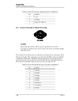
The current transducer signal connector provides pins for connection of the
current transducer (CT) signal to the Model 430; power to the CT is also
provided via this connector. The connector is a 9-pin
D-sub female connector with the shell lugs connected to the Model 430
Programmer chassis ground.
Table A-3.
Current Transducer Signal Connector Pin Definitions
Pin
Function
1
V out sense +
2
not used
3
not used
4
power 0 volts out
5
power -15 volts out
6
V out +
SIGNAL
Содержание 05100PS-430-601
Страница 2: ......
Страница 10: ...x Rev 5 List of Figures ...
Страница 12: ...xii Rev 5 List of Tables ...
Страница 18: ...xviii Rev 5 Foreword Safety Summary ...
Страница 30: ...12 Rev 5 Introduction Operating Characteristics ...
Страница 42: ...24 Rev 3 Installation Power Up Procedure ...
Страница 114: ...96 Rev 5 Operation Summary of Operational Limits ...
Страница 119: ...Rev 5 101 Remote Interface Reference SCPI Command Summary LOCK ABsorber LOCK BRIGHTness LOCK NETsetup ...
Страница 156: ...138 Rev 5 Remote Interface Reference Error Messages ...
Страница 168: ...150 Rev 5 Service Return Authorization ...
Страница 190: ...172 Rev 5 Appendix Power Supply Details Figure A 3 Model 08150PS Dimensions Top and Side Views ...
Страница 220: ...202 Rev 5 Appendix Persistent Switch Operation Flowchart Figure A 17 Persistent Switch Operation Flowchart Page 3 ...
Страница 226: ...208 Rev 5 Index ...

