


62
Rev. 5
Operation
Setup Menu : Load
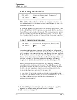
3.10.2.14 Energy Absorber Present
This picklist value indicates whether an energy absorber, such as
the AMI Model 601, is connected to the power supply system. The
default setting is NO.
It is important for this setting to be correct since the internal gain
tables of the Model 430 Programmer compensate for the additional
load of the energy absorber if present. The increased gain when an
energy absorber is present will decrease (but not eliminate) the
time required for the system to “forward bias” the energy absorber.
1
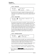
3.10.2.15 Enable External Rampdown
The External Rampdown function of the Model 430 Programmer
can be used to allow an external contact-signal to cause the magnet
to be ramped to zero field (even if it is in persistent mode) should a
fault or alarm occur in a magnet system. Signals such as low liquid
levels, cryocooler compressor faults, or abnormal temperatures can
be used to trigger a controlled magnet rampdown, even if the
magnet is in persistent mode. Refer to section 6.2 on page 157.
The external rampdown function may be enabled or disabled
according to the preference of the user. The default value is NO.
With the exception of enable yes/no, the settings and parameters
for the external rampdown function can be edited only via the
remote interface (see section 4.5.5 on page 124).
A user input for
external rampdown detection
is provided on the
rear panel of the Model 430 Programmer
2
. For further discussion of
the quench detection logic and operation, please refer to
1. The Model 430 Programmer will bring the output voltage of the power supply to the
point where the energy absorber can provide current to the magnet.
2. Refer to section A.6.2 on page 157.
+50.00 A — Energy Absorber Present?
+0.50 Vs
NO
YES
+0.00 A — External Rampdown Enabled?
+0.00 Vs
NO
YES
Содержание 05100PS-430-601
Страница 2: ......
Страница 10: ...x Rev 5 List of Figures ...
Страница 12: ...xii Rev 5 List of Tables ...
Страница 18: ...xviii Rev 5 Foreword Safety Summary ...
Страница 30: ...12 Rev 5 Introduction Operating Characteristics ...
Страница 42: ...24 Rev 3 Installation Power Up Procedure ...
Страница 114: ...96 Rev 5 Operation Summary of Operational Limits ...
Страница 119: ...Rev 5 101 Remote Interface Reference SCPI Command Summary LOCK ABsorber LOCK BRIGHTness LOCK NETsetup ...
Страница 156: ...138 Rev 5 Remote Interface Reference Error Messages ...
Страница 168: ...150 Rev 5 Service Return Authorization ...
Страница 190: ...172 Rev 5 Appendix Power Supply Details Figure A 3 Model 08150PS Dimensions Top and Side Views ...
Страница 220: ...202 Rev 5 Appendix Persistent Switch Operation Flowchart Figure A 17 Persistent Switch Operation Flowchart Page 3 ...
Страница 226: ...208 Rev 5 Index ...