149 • Schlage • ENGAGE Managed Property User's Guide
CTE Controller with Multi-Technology Readers
Installation and Commissioning
CTE Controller with Multi-Technology Readers
Device Introduction
The installation instructions outlined here are
excerpts from the devices’ Installation Instructions
in-the-box and cover the most common issues
encountered when installing the device.
Before installing the device, review the Installation Instructions for the Schlage CTE contained in the
box. Additionally, review all accessory details for the power supply, credential reader, and the
installation instructions of the locking device to ensure their interconnection and mounting
requirements.
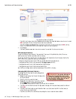
Fig. 11.55: CTE Printed Circuit Board (PCB) Diagram
Prepare to Mount the Device
Before installing, record the serial number and the intended (or installed) location. This information is
required for the Administrator to commission the device and entry into the ENGAGE account.
Tools Needed: Phillips screwdriver, the credential reader, and the locking device system. Additional
items may be needed depending on the power supply and accessories chosen.
For best results when installing the CTE, review the points below and the installation excerpts from
the installation instructions:
• Install the CTE indoors with a temperature range of -35°C to +66°C (-31°F to +151°F).
• I
nstall in a
secure location
that is not accessible by the public.
• Determine the location and interconnection wiring requirements for each component before
installing.
• Do not mount
the CTE on a metal surface and keep it at least 1 inch away from any metal. Wireless
signals can be adversely affected
• Ensure all wiring runs are as short as possible and do not exceed recommended distances, 500 feet
with 18 gauge (awg).
• Use
ONLY
stranded and appropriate wire gauge multi-conductor wire.
• Do not use any splices in any wiring connection and ensure good connections are made when using
Power Hinges or Electrical Power Transfers (EPT).
• The CTE Lock Relay can be configured to fail safe (fail unlocked) or fail secure (fail locked) by wiring
the door hardware to either NO or NC and selecting a failsafe or fail secure locking device.
• For best Wi-Fi network and Bluetooth (BLE) wireless communication, ensure the following:
• Do not mount the CTE near large metal objects or inside other metal enclosures or cabinets.
Wireless signal will not pass through metal walls.
• Mount the CTE within 10 feet of the door opening.
• Mount the CTE within communication range of the local Wi-Fi access point.
WARNING:
DO NOT USE A POWER
DRILL!
ONLY use a hand tool to install the
devices to prevent product damage.
Содержание SES20171127A
Страница 1: ...ENGAGE Managed Property 7 6 0 User s Guide...
Страница 8: ...8 Schlage ENGAGE Managed Property User s Guide...


