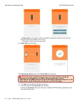
151 • Schlage • ENGAGE Managed Property User's Guide
CTE Controller with Multi-Technology Readers
Installation and Commissioning
Credential Reader Connection to CTE
The credential reader must be properly wired for
power and communication and Paired (or linked) to
the CTE for proper operation.
• When properly connected and powered up, the
attached credential reader will automatically be
recognized during the initial Power-On process.
• If the Credential Reader does not respond to
credential presentations and presents a solid
RED
LED, it is not properly wired to the CTE.
• When changing the Credential Reader, the Pairing process may need to be manually repeated.
• Follow the steps below to pair a Credential Reader with the CTE.
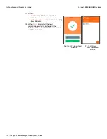
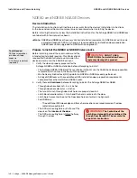
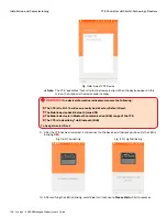
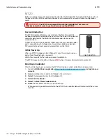
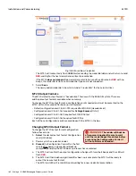
• Press and release the
Schlage
button 1 time.
• Press and release the
FDR
button 2 times.
• The Credential Reader beeps and blinks
AMBER
3 times to indicate success.
Note:
Î
The CTE
does not
control the Credential Reader beeper. A Configuration Card (CE-401-133)
is required to disable the credential reader beeper
Locking Device Installation
The CTE supports many different
types of electronic locking devices.
The installer should review the
locking device installation
instruction for the device they
intend to install and follow its
installation requirements.
Verify Success of the Installation
Once all components have been
installed, test each to ensure a
successful installation.
CTE Relay Outputs Test
The CTE has built in options to test
its installation quickly.
Each of the three output relays
(lock, alarm, and auxiliary) has
three DRY outputs and three
POWERED outputs that can be
manually activated using a push-
button on the CTE PCB.
• Press and hold any of the TEST
switches to manually test the LOCK RELAY, ALARM RELAY, and AUX RELAY.
• Both the DRY and the POWERED outputs of the relays are exercised when the TEST buttons are
pressed.
• The FAULT LED (circled) illuminates
RED
any time an overcurrent condition is detected at any of the
relay outputs.
Factory Default Reset (FDR) Overview
A Factory Default Reset (FDR) will return the CTE to its original settings as shipped from the factory.
Additionally, the following will occur.
• Removes any non-default device settings, deletes the Master Construction and User Construction
Credentials, and allows construction mode to be entered again.
• Does
NOT
have any effect on the firmware currently on the CTE or the reader.
• Does
NOT
remove the CTE from your ENGAGE account.
• The STATUS LED on the PCB lights
RED
and the Factory Default MODE lights
GREEN
.
Fig. 11.58: CTE / Reader Connection Switches
Fig. 11.59: CTE TEST Switches
Содержание SES20171127A
Страница 1: ...ENGAGE Managed Property 7 6 0 User s Guide...
Страница 8: ...8 Schlage ENGAGE Managed Property User s Guide...


