150 • Schlage • ENGAGE Managed Property User's Guide
CTE Controller with Multi-Technology Readers
Installation and Commissioning
Mount/Install the Devices
Install the Schlage CTE and all accessories as
directed in their respective installation instructions
.
CTE Installation
The Schlage CTE is provided in an enclosure that
allows the installer multiple options when mounting
in its permanent location.
The CTE is not plenum rated.
The installer should refer to the CTE Installation
Instruction and use best practices to securely mount
the enclosure. Generally, four screws into a solid wall
are adequate for a secure mount. If the location does
not adequately support the CTE, mounting anchors
should be used.
The CTE enclosure provides ample room for cable
routing in and out of the enclosure. Special attention is needed when drilling additional holes in the
enclosure to accommodate the size and number of entry or exit connectors to be used.
Power Supply Installation
When selecting and installing a power supply, refer to that components’ own installation instruction.
Use of an existing and available power supply or a Power-Over-Ethernet (POE) supply may eliminate
the need for additional power supplies.
Credential Reader Installation
The CTE supports one door opening and one wall mounted Credential Reader at a time.
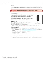
The original MT11-485 mullion reader and MT15-485 single gang readers initially available have been
updated to provide Mobile Credential compatibility MTB11-RS485 and MTB15-RS485.
Fig. 11.56: Original Readers
Fig. 11.57: Mobile Enabled Readers
The CTE is completely compatible with either the original or new Mobile Enabled Wall Mounted
Credential readers.
The electrical connections from the CTE to the Wall Mounted Reader require only power and data line
connections. Refer to the credential reader installation instructions when installing.
Table 11.2 Reader Connections
Reader - RS485
Description
POWER 12V
Reader power (red wire)
12 VDC power to RS485
POWER GND
Reader power ground (black) Electrical ground (common) for the CTE
DATA A
RS485 data A (pink)
Data A communication for RS485 reader
DATA B
RS485 data B (tan)
Data B communication for RS485 reader
WARNING:
To avoid damage to the
Schlage CTE electronics during
installation, use CAUTION when drilling
holes for the external wiring exit/entry
connector holes.
The installer should use
light drilling pressure so that the drill bit
does not penetrate the enclosure and
damages the internal Printed Circuit Board
(PCB). If the PCB is to be temporarily
removed for drilling connector holes and
wiring, use EXTREME CAUTION to ensure
the PCB is not damaged and is handled in
an electrostatically safe manner.
CTE does not support
wall mounted readers
with a keypad
(MTK15). The CTE
only supports -485
readers not weigand.
Содержание SES20171127A
Страница 1: ...ENGAGE Managed Property 7 6 0 User s Guide...
Страница 8: ...8 Schlage ENGAGE Managed Property User s Guide...


