


1 — Introduction
1-4
2902 MainStreet Technical Practices
90-2906-01 May
2002
Chassis
The chassis acts as a mechanical base for the Control card, power supply and
connectors. The top is attached with screws and, once removed, provides access to
the Control card, its modules and the power supply.
The front panel has LEDs that indicate the status of the power supply, the alarms, the
processor and the primary rate links. The rear panel has LEDs that indicate the status
of the Control card and loopbacks, and a seven-segment display that indicates the
number of major alarms. All power and signal connections are made at the rear panel.
Power supply
The self-contained power supply is mounted inside the unit, above the Control card.
It receives its power connection from the power connector module, which contains
an EMI filter, fuse holder and power switch.
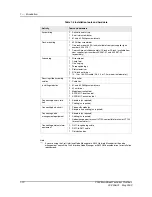
Control card
The Control card is a multilayered printed circuit board that performs functions
common to the entire system. It contains the system software and configuration
memory, and supports up to two E1 primary rate LIMs and up to two data interface
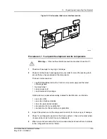
modules. Figure 1-3 shows the location of the modules.
The Control card provides connectors for network interfaces, data devices, serial
ports and external alarm devices. It also supports several LED indicators that can be
seen from the back panel (see Figure 1-2).
Figure 1-3 Control card modules
8840
Personality
modules
(Slot 2/Slot 1)
EPROMs
Interface
module
(position 2)
Interface
module
(position 1)
3 4
1 2
LIM (P1)
Jumper blocks
(J37, J40)
Jumper blocks
(J41, J44)
LIM (P2)
Содержание MainStreet 2902
Страница 1: ...2902 MainStreet Network Termination Unit Release 1 0 H T E C H N I C A L P R A C T I C E S ...
Страница 40: ...3 Mounting the unit 3 8 2902 MainStreet Technical Practices 90 2906 01 May 2002 ...
Страница 50: ...4 Ground and power connections 4 10 2902 MainStreet Technical Practices 90 2906 01 May 2002 ...
Страница 68: ...6 Connecting to the network 6 4 2902 MainStreet Technical Practices 90 2906 01 May 2002 ...
Страница 90: ...7 Connecting to data devices 7 22 2902 MainStreet Technical Practices 90 2906 01 May 2002 ...
Страница 108: ...10 Node management 10 10 2902 MainStreet Technical Practices 90 2906 01 May 2002 ...
Страница 150: ...14 CPSS 14 6 2902 MainStreet Technical Practices 90 2906 01 May 2002 ...
Страница 168: ...16 E1 circuit operating parameters 16 4 2902 MainStreet Technical Practices 90 2906 01 May 2002 ...
Страница 218: ...20 Codirectional DCM 20 6 2902 MainStreet Technical Practices 90 2906 01 May 2002 ...
Страница 234: ...22 HCM rate adaption 22 10 2902 MainStreet Technical Practices 90 2906 01 May 2002 ...
Страница 246: ...23 Cross connecting circuits 23 12 2902 MainStreet Technical Practices 90 2906 01 May 2002 ...
Страница 254: ...24 Visual indicators 24 8 2902 MainStreet Technical Practices 90 2906 01 May 2002 ...
Страница 266: ...25 Alarms 25 12 2902 MainStreet Technical Practices 90 2906 01 May 2002 ...
Страница 278: ...26 System diagnostics 26 12 2902 MainStreet Technical Practices 90 2906 01 May 2002 ...
Страница 298: ...27 Loopbacks 27 20 2902 MainStreet Technical Practices 90 2906 01 May 2002 ...
Страница 332: ...Glossary GL 8 2902 MainStreet Technical Practices 90 2906 01 May 2002 ...
Страница 343: ......
Страница 344: ... 2002 Alcatel All rights reserved 90 2906 01 95 1820 01 00 C ...