15 — E1 module operating parameters
15-12
2902 MainStreet Technical Practices
90-2906-01 May
2002
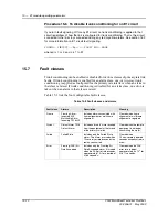
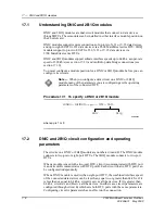
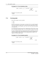
Procedure 15-6 To disable trunk conditioning for an E1 circuit
If you turn fault signaling off for any E1 circuit, no trunk conditioning is applied to that
circuit regardless of how the link is configured for trunk conditioning. That is, the circuit
connected to the link stays connected during any red or yellow alarms. See section 16.2
for more information on E1 circuit fault signaling.
CONFIG — CIRCUIT — <P
p
-
c
>
↵
— FAULT_SIG — NONE
where
p
is 1 or 2, and
c
is 1 to 31
15.7
Fault classes
Trunk conditioning can be enabled or disabled for various classes of primary rate link
faults. If trunk conditioning is enabled for an alarm class, one- or two-way trunk
conditioning is applied as configured for the primary rate interface when an alarm in
that class is raised. If trunk conditioning is disabled for an alarm class, no action is
taken when an alarm in that class is raised.
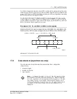
Table 15-3 lists the four configurable fault classes.
Table 15-3 Fault classes and alarms
Fault class
Alarms
Description
Clearing
Frame Framing
Alarm
Incoming AIS
Multiframe Alarm
Incoming TS16 AIS
Includes alarms associated with
frame alignment or multiframe
alignment.
Cleared when frame
alignment or multiframe
alignment is regained.
Distant Distant
Alarm
TS16
Distant Alarm
Includes alarms that are received
from the equipment at the far end
of the primary rate link.
Cleared when the remote
equipment is no longer
transmitting the alarm.
Failed
Failed State
Includes only the Failed State
alarm. This alarm is raised when
10 severely errored seconds in a
row have occurred.
Cleared when
10 non-severely errored
seconds have occurred in
a row.
Error Framing
(FAS)
Err
Rate Exceeded
Includes only the Framing Err
Rate Exceeded alarm. It is raised
when the FAS error rate exceeds
approximately 10
-3
for a period of
4 to 6 seconds.
Cleared when the FAS
error rate is below
approximately 4 x 10
-4
for
9 to 11 seconds.
Содержание MainStreet 2902
Страница 1: ...2902 MainStreet Network Termination Unit Release 1 0 H T E C H N I C A L P R A C T I C E S ...
Страница 40: ...3 Mounting the unit 3 8 2902 MainStreet Technical Practices 90 2906 01 May 2002 ...
Страница 50: ...4 Ground and power connections 4 10 2902 MainStreet Technical Practices 90 2906 01 May 2002 ...
Страница 68: ...6 Connecting to the network 6 4 2902 MainStreet Technical Practices 90 2906 01 May 2002 ...
Страница 90: ...7 Connecting to data devices 7 22 2902 MainStreet Technical Practices 90 2906 01 May 2002 ...
Страница 108: ...10 Node management 10 10 2902 MainStreet Technical Practices 90 2906 01 May 2002 ...
Страница 150: ...14 CPSS 14 6 2902 MainStreet Technical Practices 90 2906 01 May 2002 ...
Страница 168: ...16 E1 circuit operating parameters 16 4 2902 MainStreet Technical Practices 90 2906 01 May 2002 ...
Страница 218: ...20 Codirectional DCM 20 6 2902 MainStreet Technical Practices 90 2906 01 May 2002 ...
Страница 234: ...22 HCM rate adaption 22 10 2902 MainStreet Technical Practices 90 2906 01 May 2002 ...
Страница 246: ...23 Cross connecting circuits 23 12 2902 MainStreet Technical Practices 90 2906 01 May 2002 ...
Страница 254: ...24 Visual indicators 24 8 2902 MainStreet Technical Practices 90 2906 01 May 2002 ...
Страница 266: ...25 Alarms 25 12 2902 MainStreet Technical Practices 90 2906 01 May 2002 ...
Страница 278: ...26 System diagnostics 26 12 2902 MainStreet Technical Practices 90 2906 01 May 2002 ...
Страница 298: ...27 Loopbacks 27 20 2902 MainStreet Technical Practices 90 2906 01 May 2002 ...
Страница 332: ...Glossary GL 8 2902 MainStreet Technical Practices 90 2906 01 May 2002 ...
Страница 343: ......
Страница 344: ... 2002 Alcatel All rights reserved 90 2906 01 95 1820 01 00 C ...


