


1. Components Overview
71
Nu
mb
er
Name
Type
Description
Details
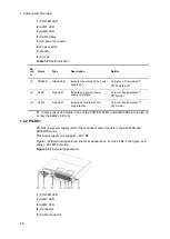
(6)
EPU 2
Connector
Standby power connector 2
To output electrical power from the power
supply module mounted in slot 2.
Connect the standby power cable bundled
with the power supply module to the
standby power connector on the back face
of the switch.
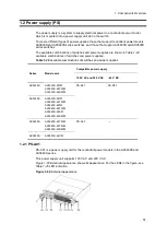
1.4.3 EPU accessories
The items listed in
are included as accessories with the
shipment of an EPU.
Table 1-37
EPU accessories
Nu
mb
er
Item
Quantit
y
Notes
1
Check list for bundled items
1
2
For Safe Operation
1
3
AC power cable
1
3m
4
Standby power cable
1
1.5m
5
Rubber pad
4
6
Rack mounting bracket
2
1 each for left and right
7
Screws
12
M3 x 6
(1) Check list for bundled items
List of the bundled items with shipment of the EPU
(2) For Safe Operation
Cautionary notes for safe use of the Switch are described.
Be sure to read through this document before using the switch.
(3) AC power cable
The cable (3 m long) is for a 100 V AC power supply unit. Use it to connect the EPU with
your electrical power equipment.
Содержание AX2400S series
Страница 3: ...Copyright Copyright C 2005 2011 ALAXALA Networks Corporation All rights reserved ...
Страница 4: ......
Страница 6: ...Preface II Find description from the AX2400S series manuals ...
Страница 7: ...Preface III Find description from the AX3640S and AX3630S series manuals ...
Страница 10: ...Preface VI ...
Страница 14: ...Contents iv ...
Страница 160: ...3 Preparation of Interface Cables and Terminals 130 ...
Страница 214: ...4 Installation of the Components 184 ...
Страница 231: ...5 Expansion Replacement and Removal 201 Figure 5 18 Inserting the fan unit 1 Fan unit slot 2 Fan unit ...


