


2. Preparation for Installation
94
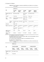
Table 2-2
General installation conditions for AX3630S series switches (AC, AC (PoE) or
DC models)
Item
Model name
AX3630S
-24T
AX3630S
-24T2X
AX3630S
-24P
AX3630S
-24TD
AX3630S
-24T2XD
Dimensions (W x D x
H)
#1
445 x 380 x 43 mm
445 x 490 x
43 mm
445 x 380 x 43 mm
Weight
#2
5 kg or less
8 kg or less
5 kg or less
Input
voltage
Rating
Single phase AC 100 to 120 V,
200 to 240 V
#3
Single phase
AC
100 to 120 V
−48 V DC
Variation
range
90 to 127.2 V AC, 180 to 254.4
V AC
90 to 127.2 V
AC
−40 to −57 V DC
Frequency
50/60
3Hz
--
Maximum input current
0.8 A @ 100
V AC
0.9 A @ 100 V
AC
5.8 A @ 100 V
AC
1.5 A @
−48 V
DC
1.8 A @
−48 V
DC
0.4 A @ 200
V AC
0.5 A @ 200 V
AC
--
--
--
Maximum power
consumption
75 W
89 W
580 W
70 W
82 W
Maximum heat
emission
270kJ/h
321 kJ/h
757 kJ/h
#4
252 kJ/h
296 kJ/h
#1: Excluding the dimensions of connectors.
#2: Weight of the main device only. The weight of cables, rack mounting brackets, memory
cards and transceivers are excluded.
#3: The power cable bundled with the Switch is only applicable to 100 V AC.
#4: Heat emission of the Switch only.
Table 2-3
General installation conditions for AX3630S series switches (redundant power
models)
Item
Model name
AX3630S-24S2XW
AX3630S-48TW
AX3630S-48T2XW
PS-A01
mounted
PS-D01
mounted
PS-A01
mounted
PS-D01
mounted
PS-A01
mounted
PS-D01
mounted
Dimensions (W x D
x H)
#1
445 x 440 x 43 mm
Weight
#2
9 kg or less
Содержание AX2400S series
Страница 3: ...Copyright Copyright C 2005 2011 ALAXALA Networks Corporation All rights reserved ...
Страница 4: ......
Страница 6: ...Preface II Find description from the AX2400S series manuals ...
Страница 7: ...Preface III Find description from the AX3640S and AX3630S series manuals ...
Страница 10: ...Preface VI ...
Страница 14: ...Contents iv ...
Страница 160: ...3 Preparation of Interface Cables and Terminals 130 ...
Страница 214: ...4 Installation of the Components 184 ...
Страница 231: ...5 Expansion Replacement and Removal 201 Figure 5 18 Inserting the fan unit 1 Fan unit slot 2 Fan unit ...


