


5. Expansion, Replacement and Removal
189
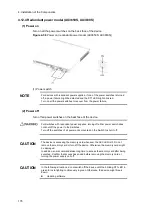
When moving the redundant power model, do not hold the handle of the power
supply unit or the fan unit. The handle can come off and the device can fall, which
might cause injury. Or the EPU might be distorted to cause a fire or an electric
shock.
CAUTION
Prior to mounting/dismounting the power supply module, turn off the switch of it.
CAUTION
Do not touch the parts or the soldered surfaces on the power supply module. For
storage, put the module in an antistatic bag.
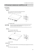
(1) Removing
[Step 1]
Check the EPU and the slot from which backup power is supplied to a device. Turn off the
power supply module mounted in the slot.
[Step 2]
Turn off the main device.
[Step 3]
Disconnect the standby power cable from the main device and the EPU.
[Step 4]
Disconnect the AC power cable from the main device.
[Step 5]
Remove the main device.
[Step 6]
The EPU and the power supply module used for a backup power supply unit to the switch
can be reused for other switches. Place them as they are if you intend to use them
repeatedly, or else, remove them.
When the EPU is used with the removed power supply module, install the blank
panel. If you use the switch without attaching the blank panel, you might be injured
by a moving part. In addition, if foreign objects fall into the switch, the switch might
no longer work properly.
(2) Installing
[Step 1]
Install the switch.
Содержание AX2400S series
Страница 3: ...Copyright Copyright C 2005 2011 ALAXALA Networks Corporation All rights reserved ...
Страница 4: ......
Страница 6: ...Preface II Find description from the AX2400S series manuals ...
Страница 7: ...Preface III Find description from the AX3640S and AX3630S series manuals ...
Страница 10: ...Preface VI ...
Страница 14: ...Contents iv ...
Страница 160: ...3 Preparation of Interface Cables and Terminals 130 ...
Страница 214: ...4 Installation of the Components 184 ...
Страница 231: ...5 Expansion Replacement and Removal 201 Figure 5 18 Inserting the fan unit 1 Fan unit slot 2 Fan unit ...


