


1. Components Overview
43
Num
ber
Name
Type
Description
LED
bright
ness
Details
(7)
T/R
Green
LED
Blinking green
Normal
Sending or receiving frames.
Low
#3
(8)
1-48
Green/Ora
nge LED
Indicates the
operating status
of a
10/100/1000BA
SE-T Ethernet
port.
Lit in green
Normal
A link is established.
Low
#3
Blinking green
Normal
A link is established and
frames are being sent or
received.
Low
#3
Lit in orange
Normal
Detecting line disturbances.
Low
#3
Off
--
A link failure or block when
the green ST1 LED is lit.
#4
(9)
RESET
Button
(momentar
y)
Manual RESET
button of the
device
#5
--
--
Restarts the device.
(10)
Display
--
Not supported.
(11)
BACK
Button
Not supported.
(12)
ENTR
Button
(13)
FWRD
Button
#1: Blinking green over a long period of time (on: 0.5 seconds; off: 5 seconds)
#2: Operating in power control (brightness) mode or off mode
#3: Operating in power control (brightness) mode
#4: In off mode, a link might be established, frames might be sent or received, or line
disturbances might be detected.
#5: The switch is behind the front panel. Use a small-head screwdriver to press it.
When attempting to push the RESET button, do not use a tool with a fragile tip, a
pin or a paper clip, which can be caught or dropped inside the switch and will not be
taken out. A fire or an electric shock might be caused.
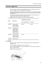
1.1.14 AX3650S-20S6XW
The AX3650S-20S6XW model has the following hardware specifications:
Ethernet 10/100/1000BASE-T ports: 4
SFP slots: 20
SFP+ slots: 6
Содержание AX2400S series
Страница 3: ...Copyright Copyright C 2005 2011 ALAXALA Networks Corporation All rights reserved ...
Страница 4: ......
Страница 6: ...Preface II Find description from the AX2400S series manuals ...
Страница 7: ...Preface III Find description from the AX3640S and AX3630S series manuals ...
Страница 10: ...Preface VI ...
Страница 14: ...Contents iv ...
Страница 160: ...3 Preparation of Interface Cables and Terminals 130 ...
Страница 214: ...4 Installation of the Components 184 ...
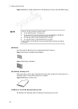
Страница 231: ...5 Expansion Replacement and Removal 201 Figure 5 18 Inserting the fan unit 1 Fan unit slot 2 Fan unit ...


